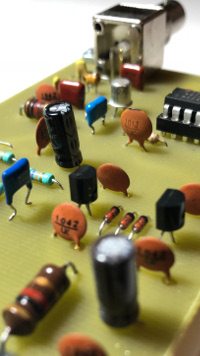
Let's talk about electronics
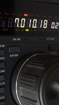
Radio:
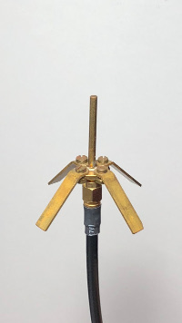
Antennas:
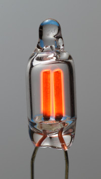
Gas discharge and glow lamps:
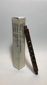
Radiation detection:
General projects:
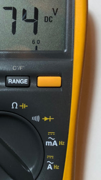
General tools and tips:
A few remarks
Not everybody around the world describes electronics in the same way: the
convention used on this page is strongly inspired by the European habits and
it may differ from what you're used to.
For example, the voltage is symbolized by the letter U, the current by
the letter I, resistors are drawn with a rectangular symbol, the
current flows from the positive terminal to the negative terminal and the
voltage is represented by an arrow pointing from the positive to the negative
potential, in the same sense as the electric field.
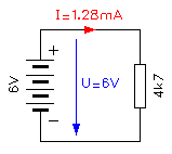
Some of the conventions used on this site.
On the schematic diagrams of this site, component values are expressed with
an "abbreviated engineering notation", where the multiplier (or
unit symbol) is also used as decimal point.
So, a resistor marked "1M5" is 1.5 MΩ, another resistor
marked "0R22 2W5" is 0.22 Ω - 2.5 W, a capacitor
marked "8n2" is 8.2 nF or a Zener diode marked "5V1
0W5" is 5.1 V - 0.5 W.
Of course, a capacitor marked "100n" is a 100 nF one (which is
0.1 μF, if you prefer).