Circuit diagram of the Ruhmkorff coil.
One day a fiend of mine showed up with a box full of Geissler tubes and a Ruhmkorff coil. He said his grandfather built the tubes by blowing the glass around 1900, more than one century ago! He wanted to see if the tube still worked, but a first attempt of powering them with the original Ruhmkorff coil failed. Than, we tried with a CCFL (Cold Cathode Fluorescent Lamp) lamp driver circuit found in an old laptop computer, but this failed as well. At that time, we had no idea of the voltage required to strike the tubes and, of course, we didn't want to break or blow up these precious tubes with too much power. So we decided to buy a brand new Geissler tube (yes, they are still manufactured) and designed a dedicated power supply.
A Geissler tube is the ancestor of the modern neon sign tubes commonly used for advertising. Today it's mainly a decorative glowing object, a scientific curiosity and a nostalgic souvenir of the past. It's composed by a sealed glass tube of any shape, usually between 10 cm and 1 m in length. It has two electrodes, one on each end, while the interior is evacuated and filled with a low pressure gas (something like 1 mbar). A current flowing from the electrodes through the gas make the gas glow and fluorescent materials used to build the tube glow as well. The gas determines the color of the glow: air will glow bluish, neon will glow red, hydrogen will glow pink, and so on. Some elements are often added to the glass to make it also glow and determine its color: the most common is uranium glass that glows yellow-green. Sometimes Geissler tubes are mounted inside bigger glass tubes filling the space in-between with glowing powders or liquids. Sometimes, special targets can be found inside the tube for some more special effect (see the picture section below). As common neon tubes, Geissler tubes requires a high striking voltage, and once the tube is on, the voltage across it drops to a lower sustaining voltage with little dependence on tube current. Geissler tubes were invented by Heinrich Geissler in 1857 and had a large impact on the development of many modern devices such as fluorescent lamps, flash lamps, X-ray tubes, cathode ray tubes, and many others.
The historic method for powering these tubes is with a Ruhmkorff coil. It requires only common simple materials and can be homebrewed, even if it's a long and tedious task. The Ruhmkorff coil is an electromechanical device with close relationship with transformers and relays. It's able to step-up the voltage of a battery and generates high voltage pulses, strong enough to strike Geissler tubes. The primary is usually composed with a small number of turns (tens or hundreds) of thick wire while the secondary has a many more turns (several thousands) of very thin wire. Some insulation techniques are required to avoid arcing inside the coil such as insulating paper foils between layers or splitting the secondary in many insulated smaller windings connected in series. The basic schematic is shown in the figure below and works as follows:
Circuit diagram of the Ruhmkorff coil.
At the beginning the current flows from the battery through the primary of the coil, through the switch (which is normally closed) and back to the battery. As the current increases and the magnetic field builds up in the core of the coil, it attracts the switch that will suddenly open the circuit, collapsing the magnetic field and inducing a high voltage surge in the windings. Since the secondary winding has many more turns than the primary, the surge on the secondary will be proportionally higher and peaks of several kilovolts are easily obtainable. As the magnetic field disappears, the switch closes again and the cycle repeats itself. Working Ruhmkorff coils make a buzzing noise and a spark can clearly be seen on the switch contacts. The capacitor connected in parallel with the switch makes a resonant circuit and quenches the arc in the switch (making it last longer) and improves the overall efficiency, but a simple and small coil can work without it.
The original coil of my friend's grandfather was built with silk insulated copper wire and the capacitor was made with a stack of newspaper sheets and aluminum foils. Everything was installed on a fine walnut tree wooden base and the contacts were made with machined brass screws. The coil didn't work at the first attempt, some foils of the capacitor were loose and the oxidation on the contacts was "one century thick". After cleaning the contacts and removing loose aluminum foils we brought the coil back to life and we could power short tubes. The pictures below show the working Ruhmkorff coil.
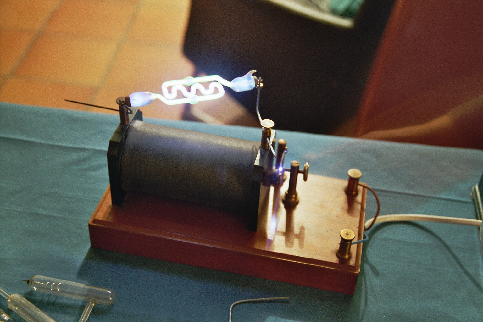
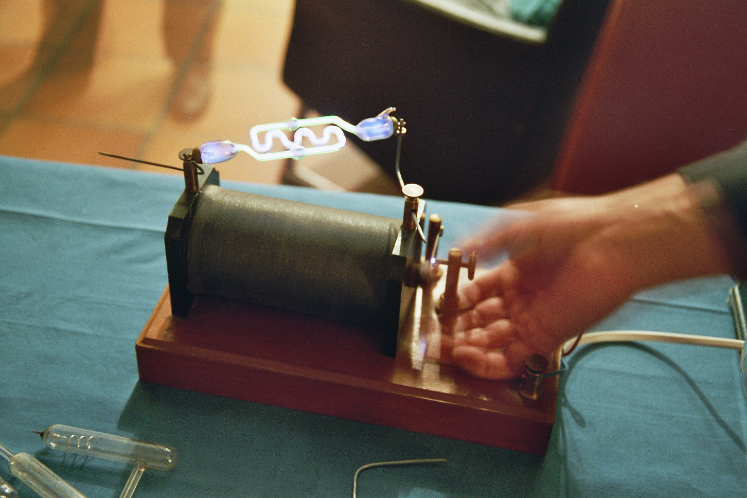
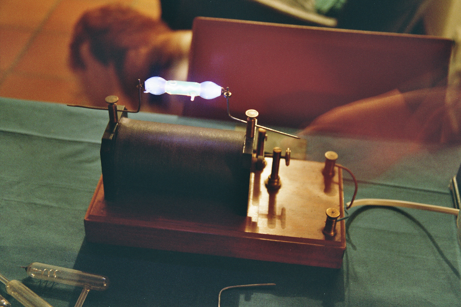
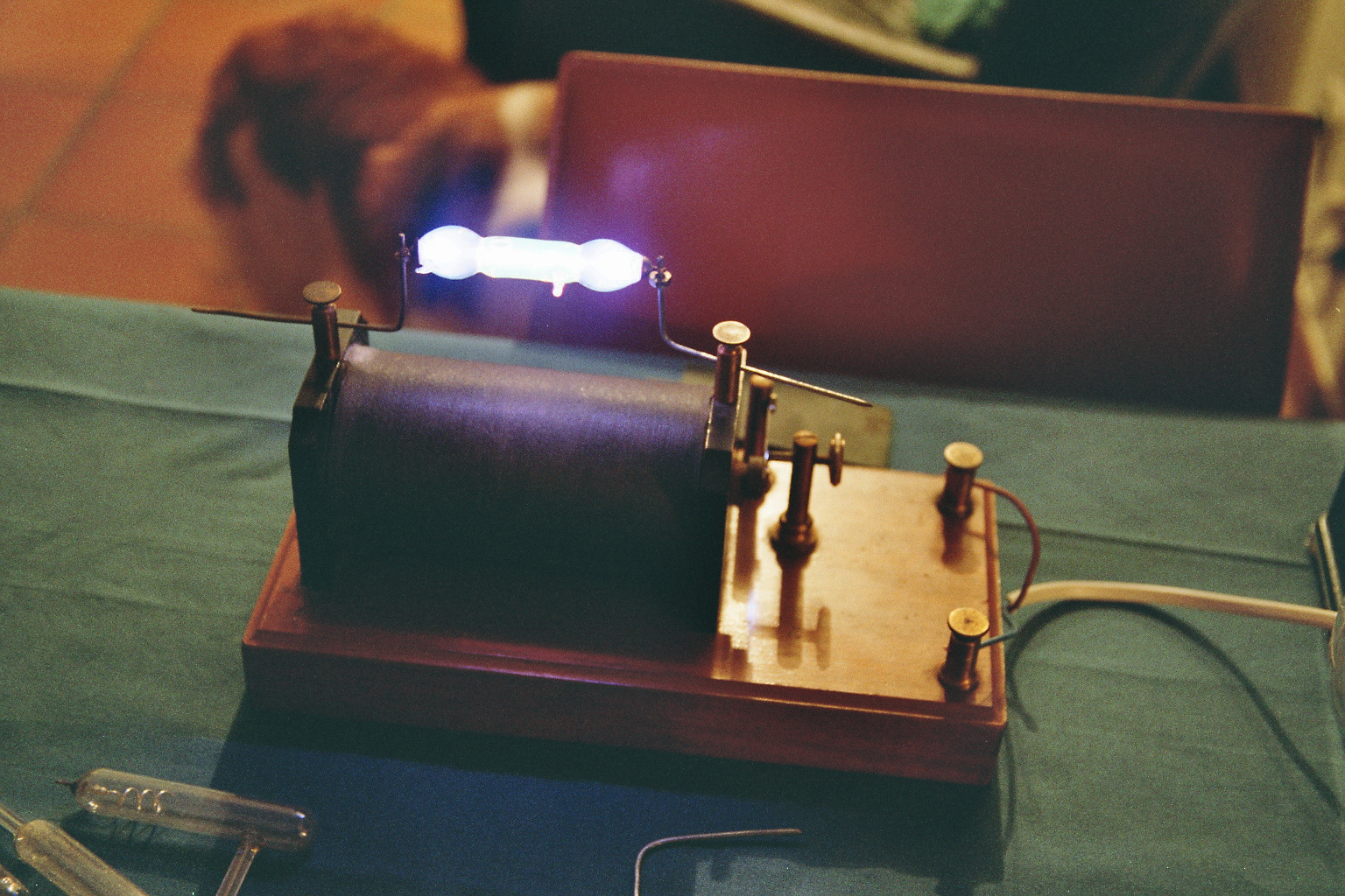
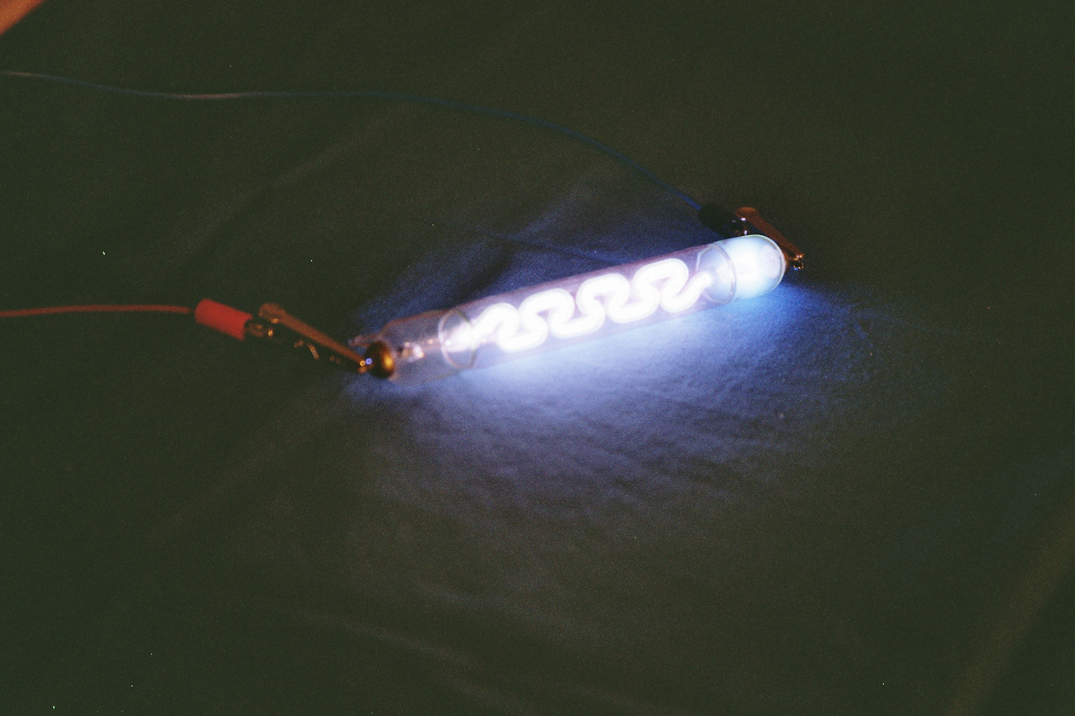
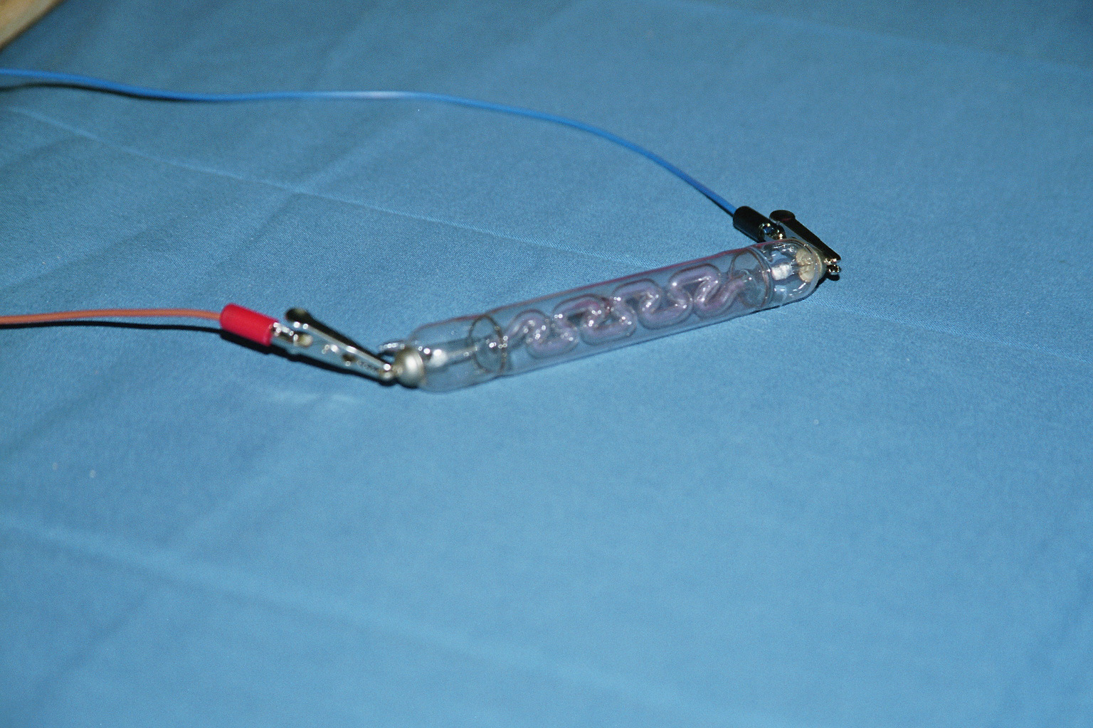
Four pictures of the working Ruhmkorff coil with two different Geissler tubes (click to enlarge).
Please remark the "ghost hand" adjusting the spark gap of the switch due to the long exposure.
The longest tubes didn't work because the output voltage was too low. Increasing the voltage wouldn't be a problem, just using a higher battery voltage would be enough (we used 12 V), but we decided not to take the risk since we didn't know how the insulation of the coil survived.
We weren't able to find any data about neither striking and sustaining voltages nor operating currents before start playing with real tubes, but the experience with the Ruhmkorff gave us a staring point: the shortest tubes required around 2 kV, longer ones probably more. They didn't work with the CCFL driver because it only produces 700 V.
A neon sign transformer could probably do the job, but this idea was discarded because it could provide too much power and destroy the tubes and also because we didn't have one.
Building a new Ruhmkorff coil today is still possible today, but winding by hand something like 10'000 turns was considered too tedious and another solution had to be considered. Fortunately, there is one common component very similar to a Ruhmkorff coil that is mass produced nowadays: the ignition coil of gasoline engines! And it's easy to source, too: just ask for scrap coil in a garage and maybe you can even get one for free. Than all you need is a circuit to simulate the contact breaker points of the engine. The electronics is very simple and is based only on junk-box parts. The schematic diagram is shown below:
Circuit diagram of the power supply (click to enlarge).
U1 is an astable oscillator based on the famous NE555: two trimmers R2 and R4 allow adjusting independently the ON and the OFF time of the generated square wave. U2 is another NE555 and is just used as inverter. It's not possible to use a single NE555 in this configuration because, to generate an inverted waveform, R1 and R2 would be too small and too much current will flow in U1's pin 7. MOSFET T1 will power (charge) the coil for a time that can be adjusted between 70 μs and 1.5 ms (with R4), and that wait between 7 and 20 ms (adjusted with R2). In other words, R4 adjust the energy of each pulse and R2 the frequency of the pulses; both control the brightness of the lamp.
T1 is a high power MOSFET capable of switching 600 V and 9 A with an RDS,ON of only 0.75 Ω. It deserves a nice heat-sink. Usually the MOSFET sees only low voltages (tens of Volts), but when something goes wrong with the coil or with the lamp, high voltage surges are possible, therefore choosing a strong MOSFET is a good idea. Diodes D4 and D5 are fast switching diodes and protect T1 against negative surges. DZ1 will clamp any surge higher than 400 V helping T1 surviving in case of high voltages spikes. These diodes can easily be found in switching (PC) power supplies. The circuit will work without them, at a higher risk of blowing up T1 when something is wrong with the lamp.
Modern ignition systems charge a capacitor with several hundred volts and than discharge it in the coil obtaining a higher output voltage, but this would complicate the circuit, so the coil has been powered directly with 12 V and no charge capacitor is used. This proved to be enough to strike Geissler tubes. A very important detail is the spark gap SG1 at the output of the coil. This spark gap is composed by two brass electrodes about 2 mm apart. Without the spark gap, if the lamp is suddenly disconnected, very high voltage pulses are generated (several tens of kilovolts) and arcing may happen inside the coil (destroying it) or dangerous voltages may appear on the primary blowing up the MOSFET. With the spark gap, the output voltage is limited by the voltage required to strike a spark in the gap and even with the lamp disconnected nothing dangerous happens. If the gap is too small some tubes may not work, if it's too big it won't be affective, but its size is not critical and can easily be adjusted. The original idea was to have a spark gap that can produce a nice Jacob's ladder, but the circuit wasn't powerful enough for this... we only have a short spark in the middle.
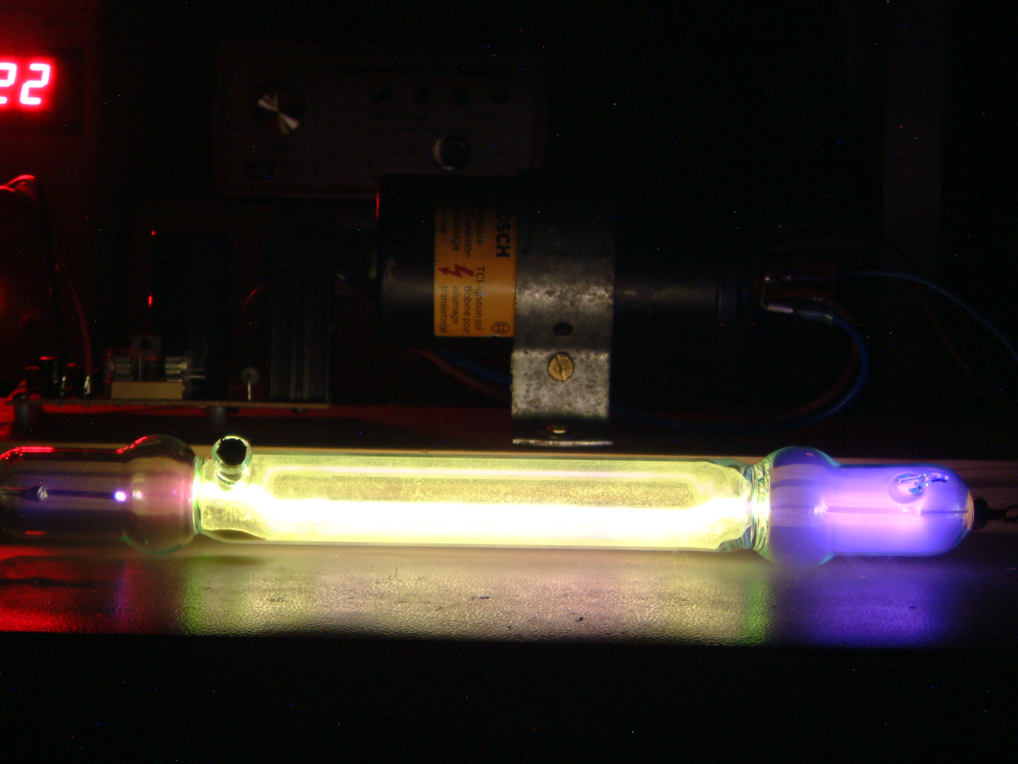
The power supply (and a modern Geissler tube) is visible in the pictures below:
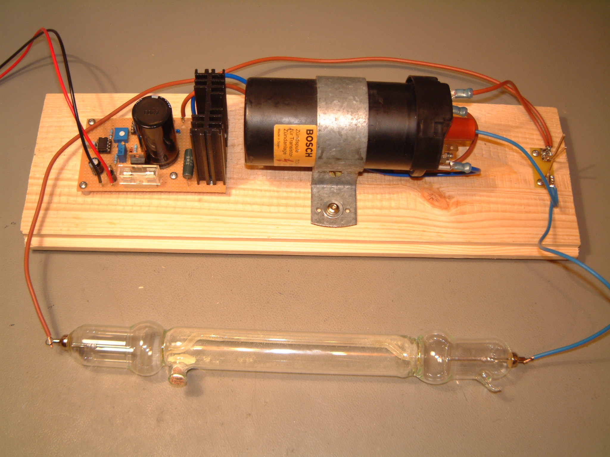
High voltage power supply with a modern Geissler tube (click to enlarge).
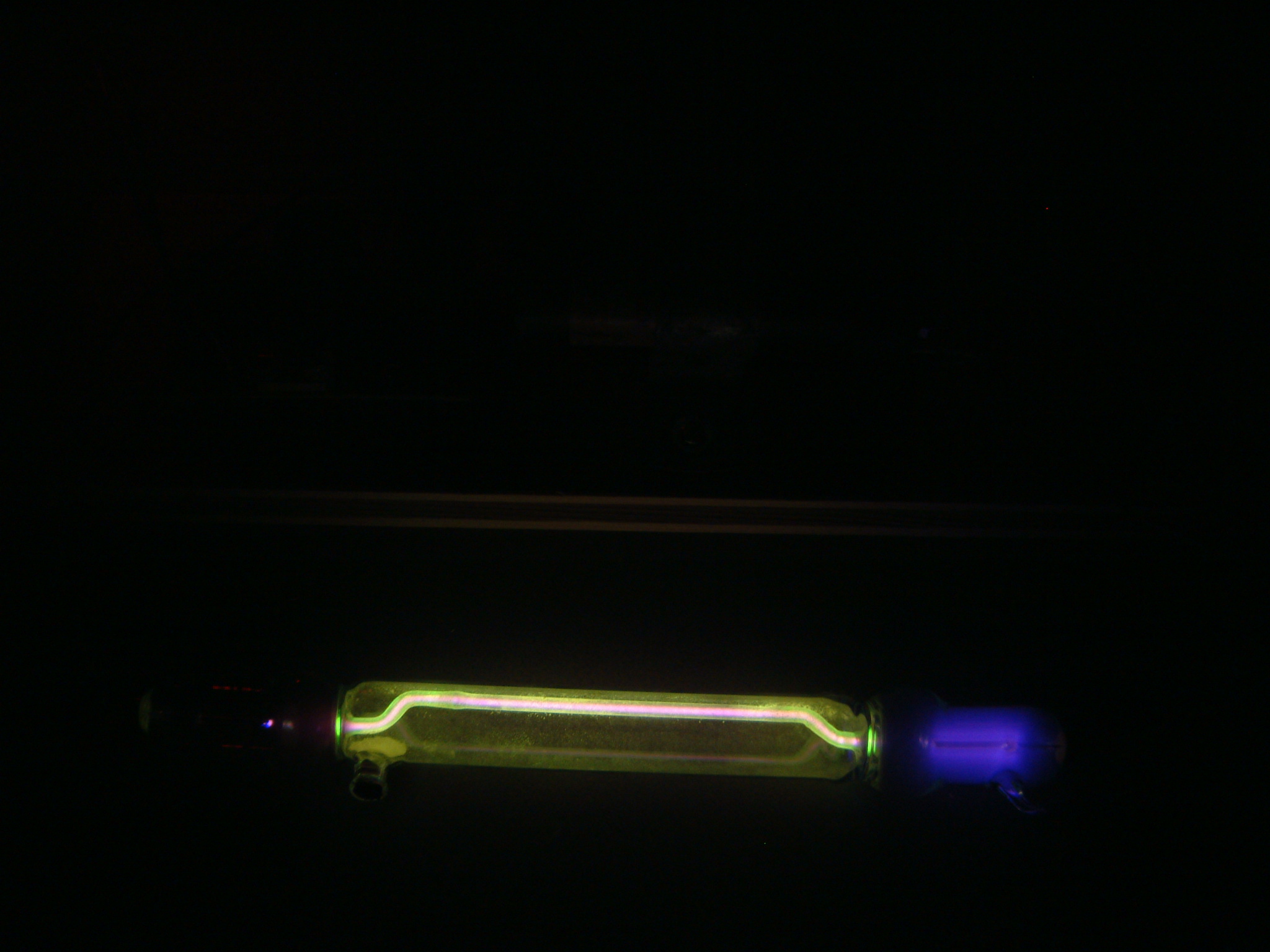
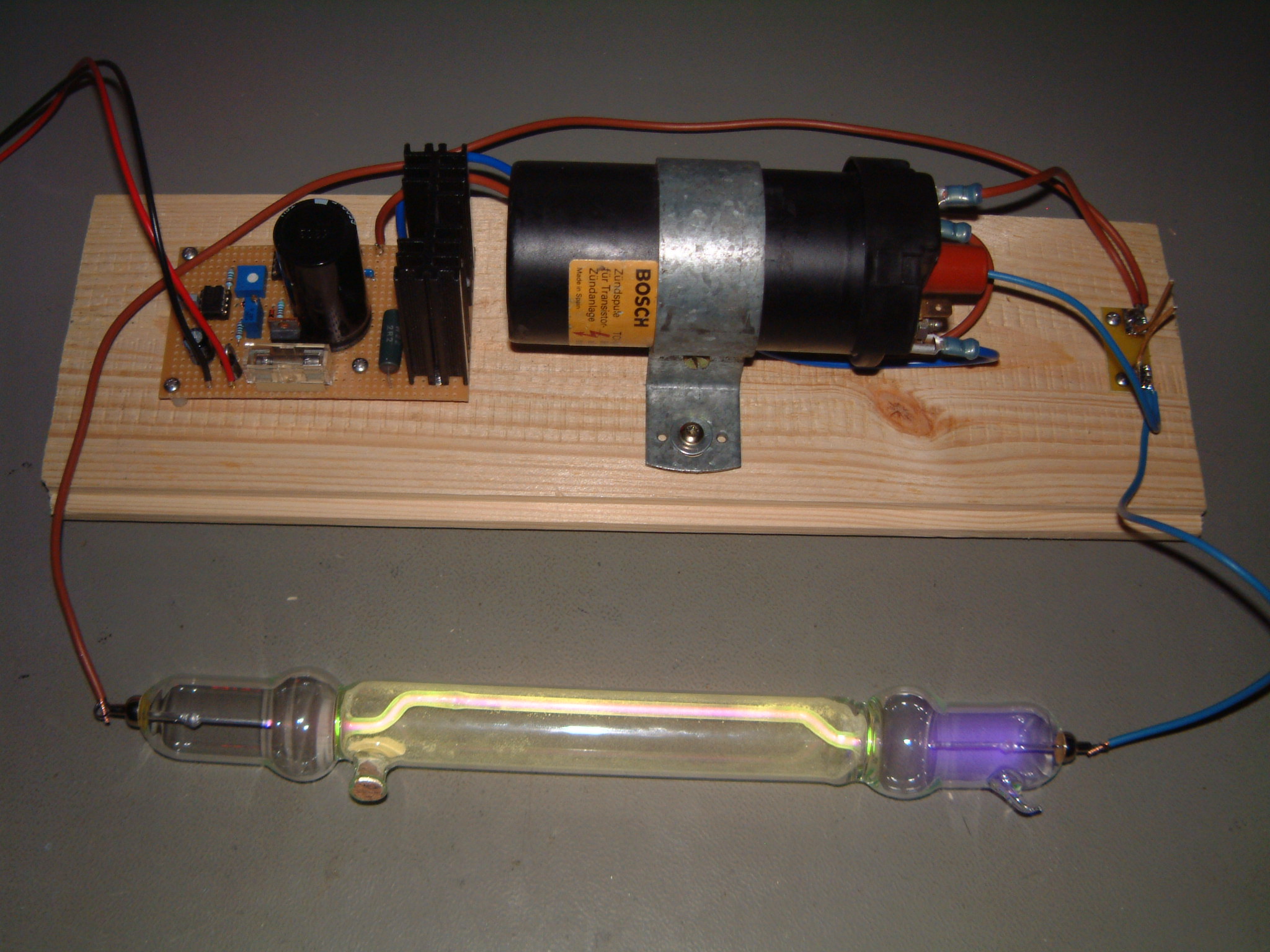
Modern Geissler tube glowing in the dark (click to enlarge).
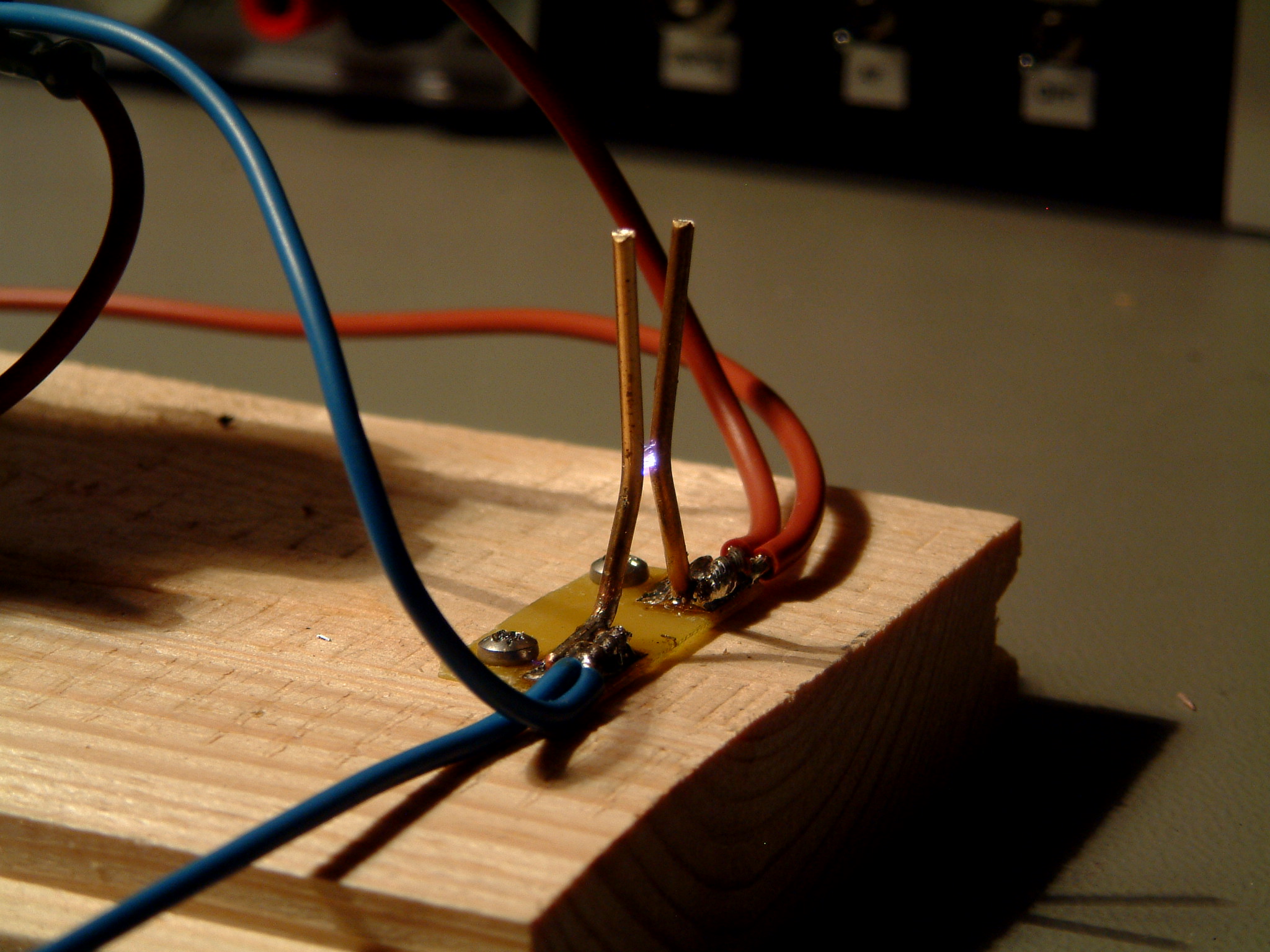
Close-up of the spark gap (click to enlarge).
A few works about the danger of high voltage. This circuit isn't more dangerous than the ignition system of a gasoline engine, but still high voltages are dangerous and you should build it and use it only if you know what you are doing. Never touch the high voltage part of the circuit while it's running and beware that common insulated wire is not good for high voltage. If you don't have high voltage cables and use common wires, don't touch them and make sure they are far from nay other metal object. In any case, build this circuit at your own risk.
R6 and C5 form and RC filter to prevent the power supply line to radiate RF noise coming from the coil. R5 and C1 form another RC filter allowing a quite power supply for the square wave generator. D3 protects the circuit against an accidental polarity reversal while connecting the circuit. The whole circuit is powered with 12 VDC and uses only about 300 mA. The current pulses in the coil are much higher, but C5 acts as local energy storage (the bugger, the better) and prevents these pulses from flowing in the power supply line.
Sparks generate radio frequency noise and interference. No serious measures are taken in this circuit to prevent interference (R6 and C5 are definitively not enough) and therefore it should be used only inside a Faraday's cage or a shielded container.
Before connecting a tube, the high voltage generator was tested alone on the spark gap. As one can see in the picture below, it produces nice spikes of high voltages, limited by the spark gap to about 9.5 kV. Adjusting the gap will modify the voltage and around 10 kV is good for Geissler tubes.
Please remark that in this case the output terminal of the coil generates positive pulses, but this depends on how the coil is winded and a different coil my have the opposite polarity.
Generator output voltage without tube, limited by the spark gap.
When connecting a Geissler tube to the output it will limit the voltage to its own striking voltage, the tube will glow and the spark will disappear. In the figure below a modern tube is connected and we can see that it strikes at about 1.5 kV. Older tubes required a higher voltage, between 2 and 4.5 kV, depending on the length. The reason why the old tubes were harder to strike is unknown, but most probably the pressure inside the tube is not low enough. Either some air leaked inside during all these years or the pump used to evacuate them was not very efficient. The color of the gas glow of these old tubes is blue, meaning that the gas inside is most probably air: still, this doesn't tell if there was a small leak or if the pressure was initially high.
Generator output voltage with a modern Geissler tube connected.
Of course, the funniest part is watching the tube glow... Let's start with a very simple one, shown below, which is just a straight tube, very very similar to modern neon signs. The color of the glow looks more bluish in reality than in the picture and the glass has no glowing additives.
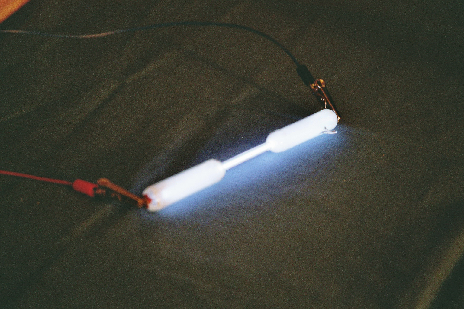
Very simple straight tube (click to enlarge).
The following four tubes are a bit more complex with a lot of bends and are composed with two different kind of glass. The green glow is due to uranium doped glass which was pretty common one century ago.
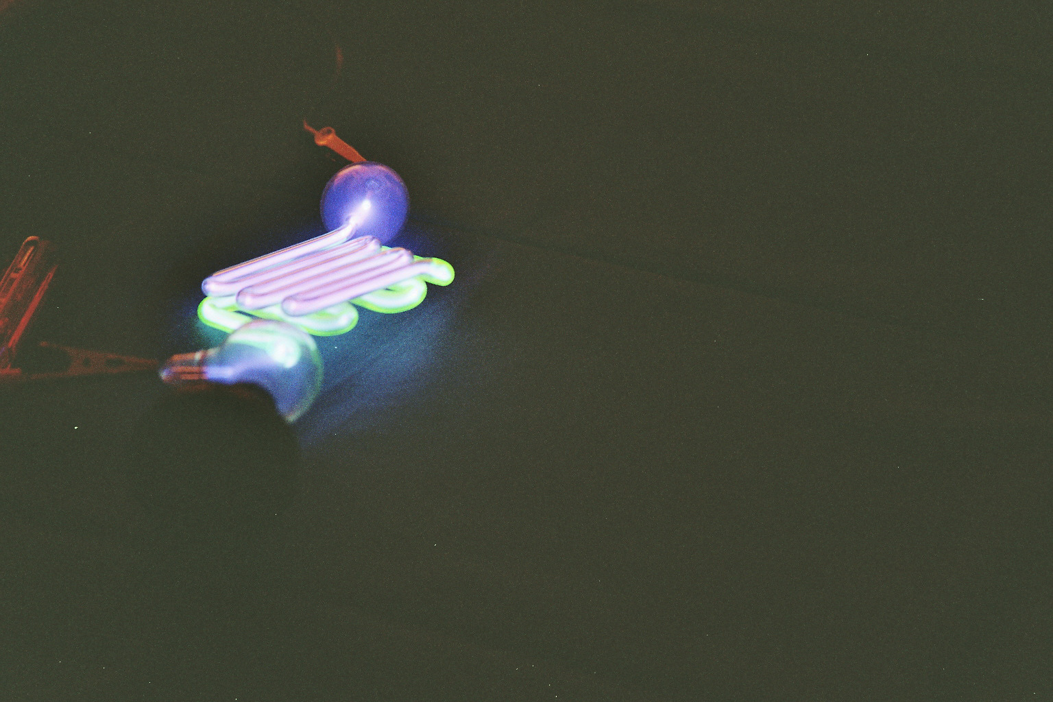
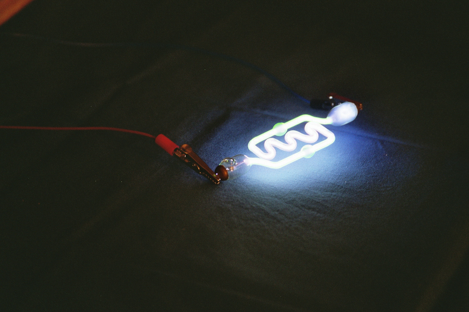
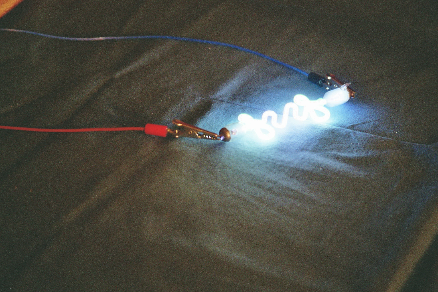
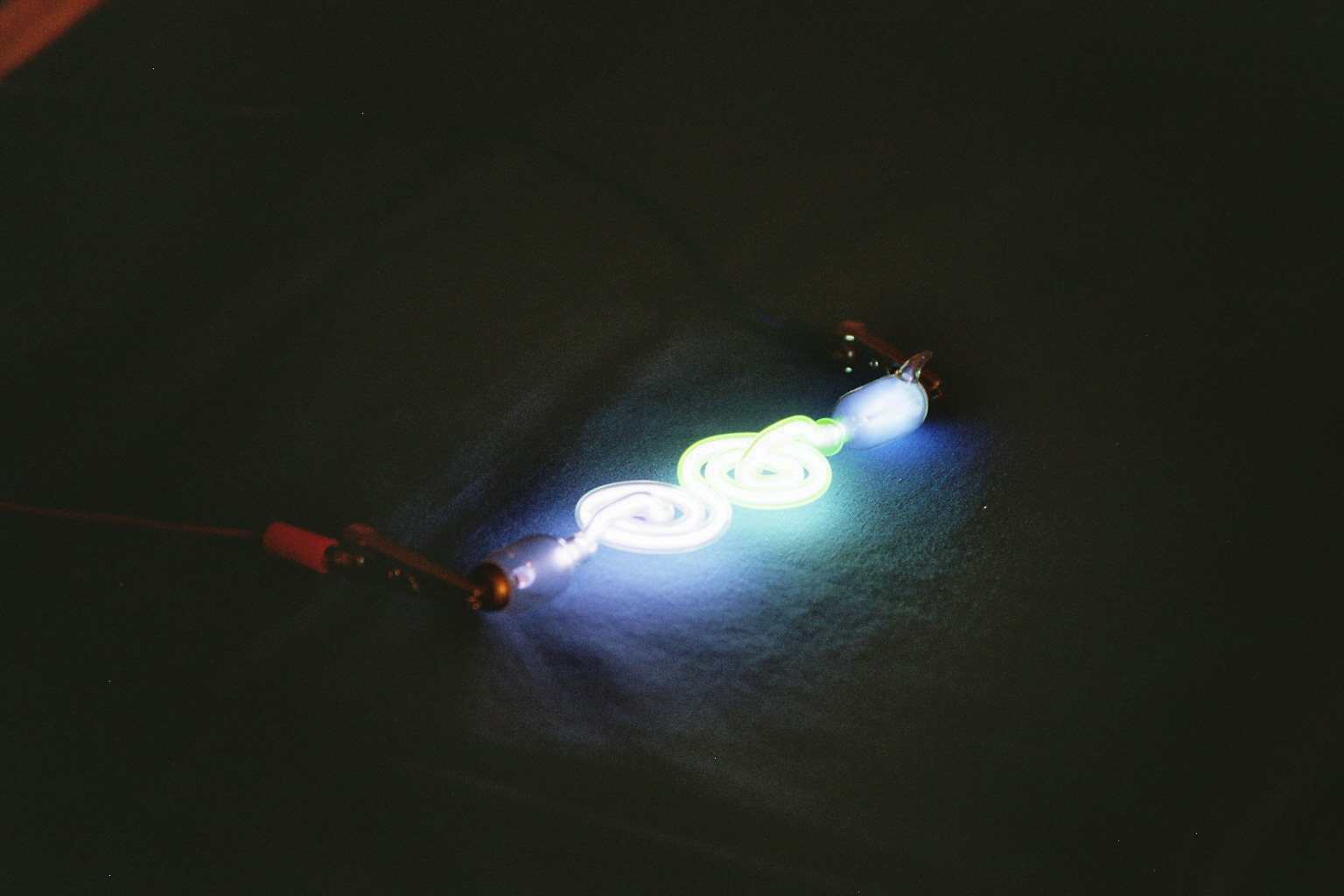
Very simple tubes with no outer tubing. The green glow is due to uranium glass (click to enlarge).
The following three tubes are even more complex since they have an outer tubing containing the gas discharge tube. Unfortunately the space in-between was empty, but we can imagine that it was originally filled with a fluorescent powder or liquid for some advanced glowing effect.
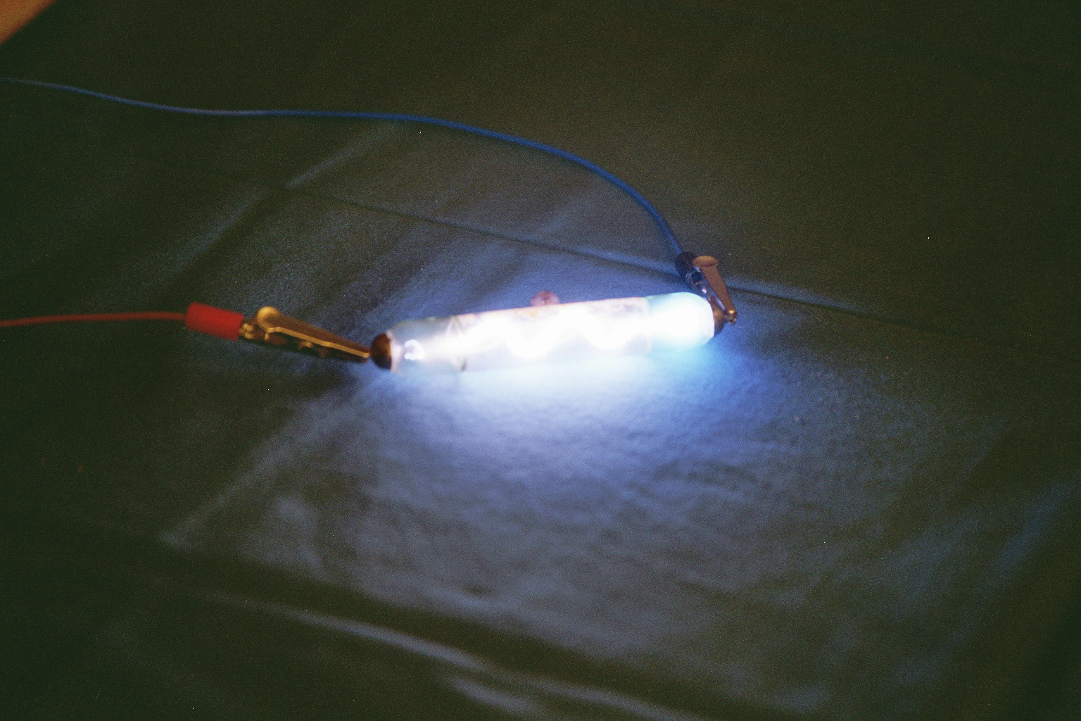
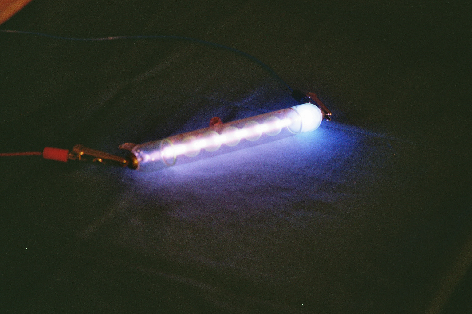
These tubes have an outer tubing, but it's unfortunately empty and there is no special glow (click to enlarge).
Below you can see a very complex luxury tube with a wooden base. It's composed by several colored glowing glasses. It has an outer tubing but it's empty. Since this tube is quite long (about 50 cm) it's interesting to remark the different glow between the electrodes: the cathode (negative) has a much larger glow than the positive. This difference is hard to see when the tube is short or when the electrodes have different shapes.
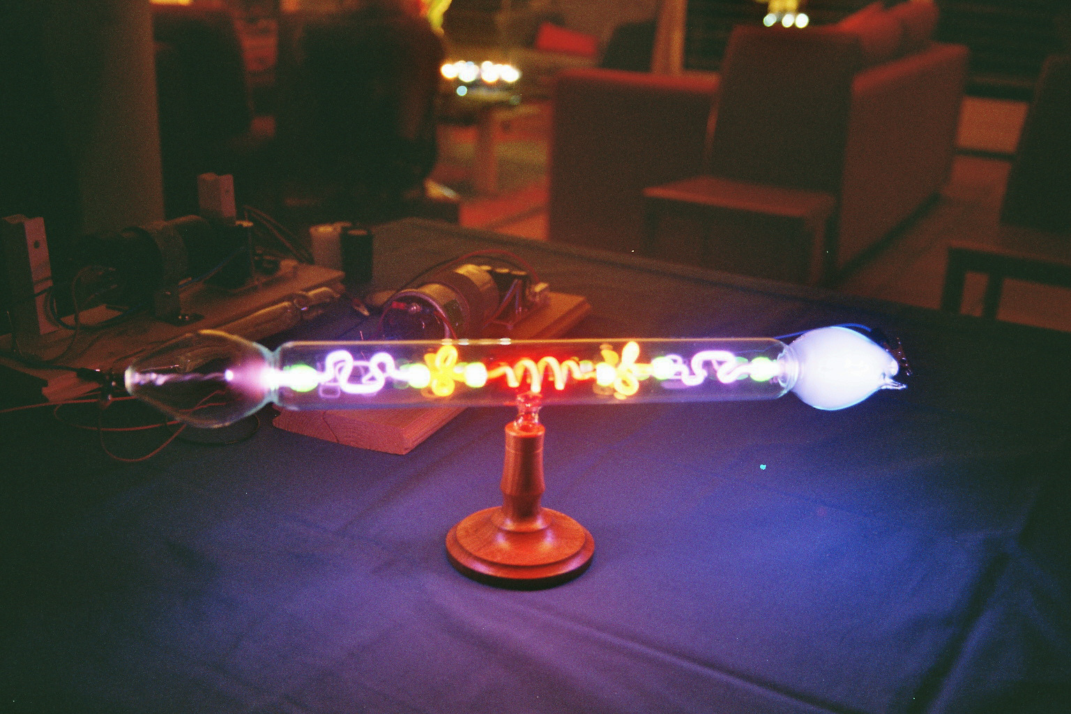
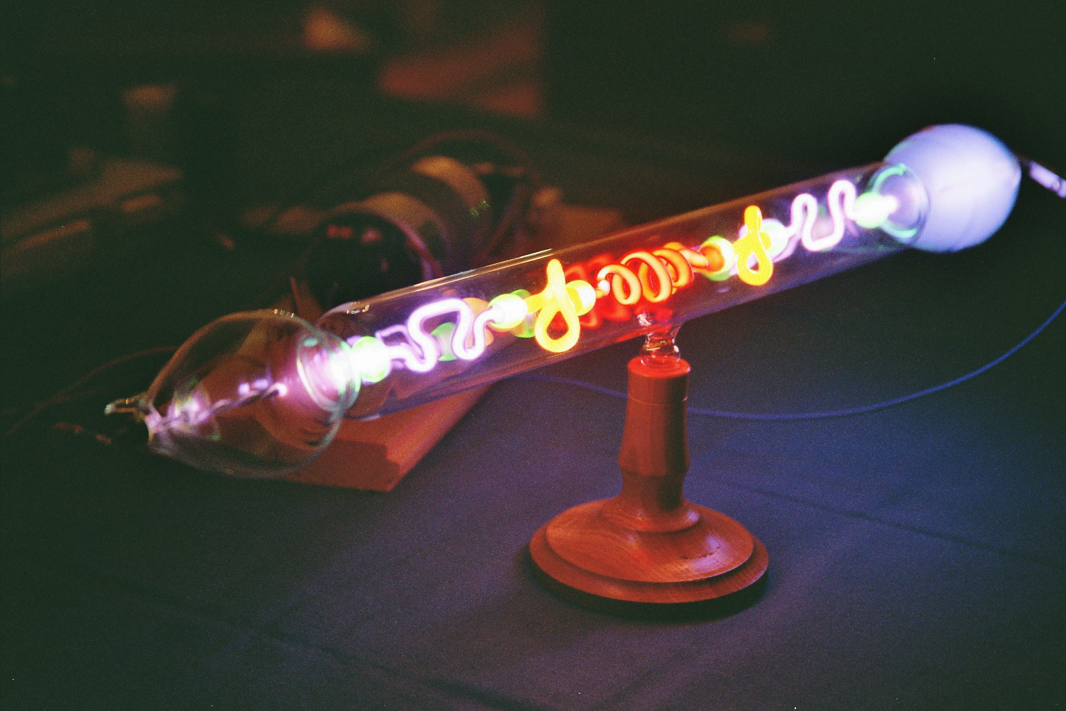
Complex tube made of different kind of glowing glass (click to enlarge).
But we were lucky and my friend still had some tubes filled with fluorescent outer liquid. These two are filled with a green (left picture) and a red (right picture) glowing liquid.
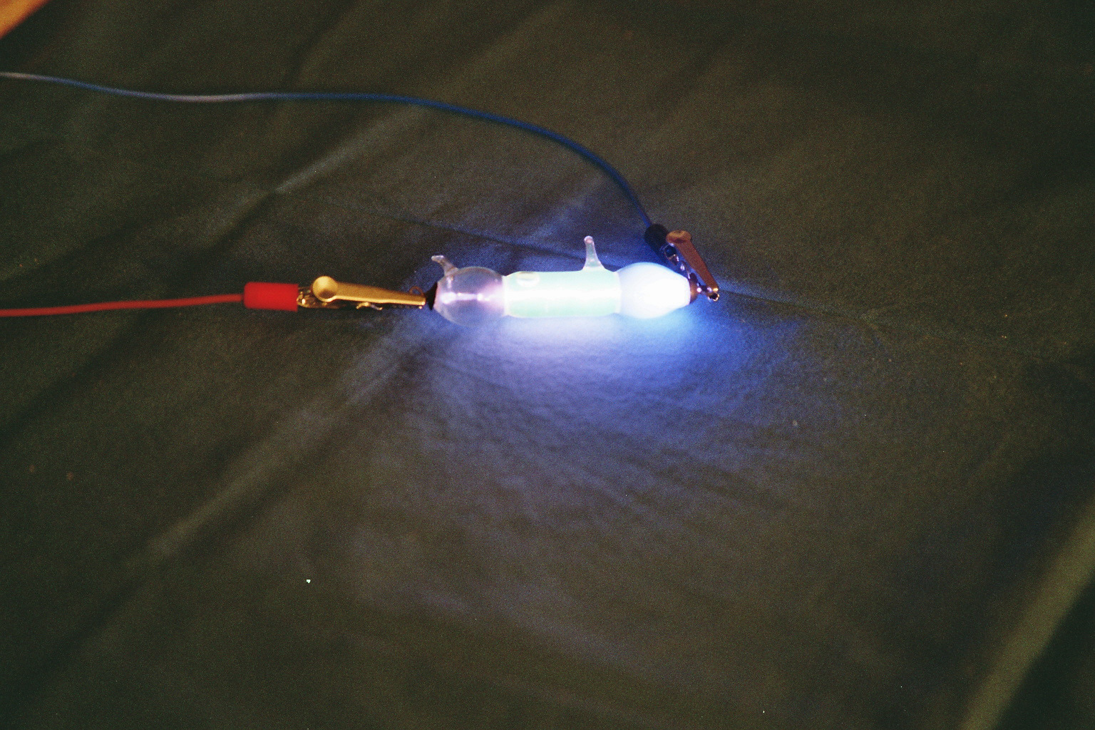
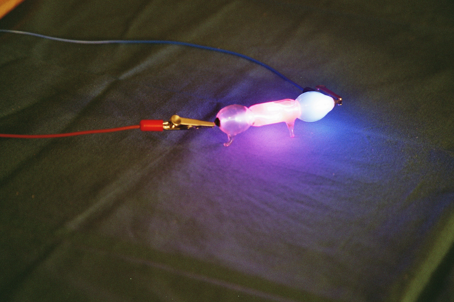
These tubes have an outer tubing filled with a fluorescent liquid (click to enlarge).
The next tube is a luxury one, since it has its own glass stand. The lower part has an outer tubing filled with a red glowing liquid while the upper part is made of uranium glass and glows green.
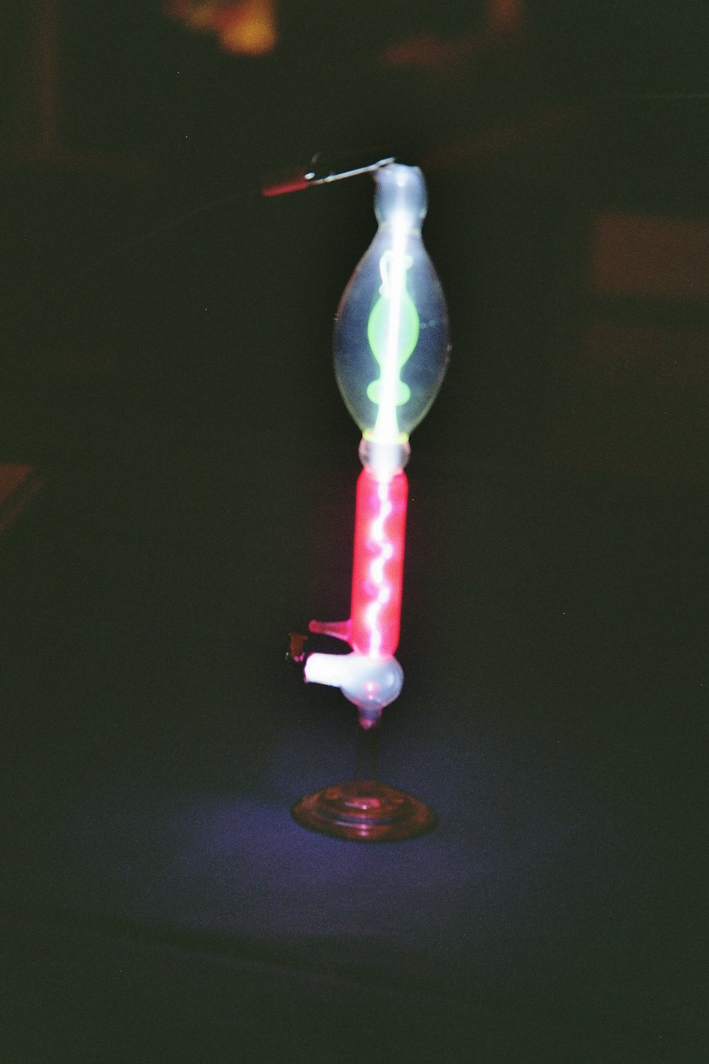
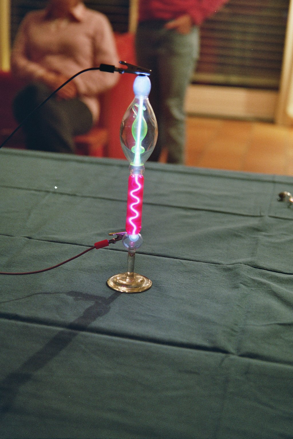
Geissler tube with liquid filling of the outer tube (click to enlarge).
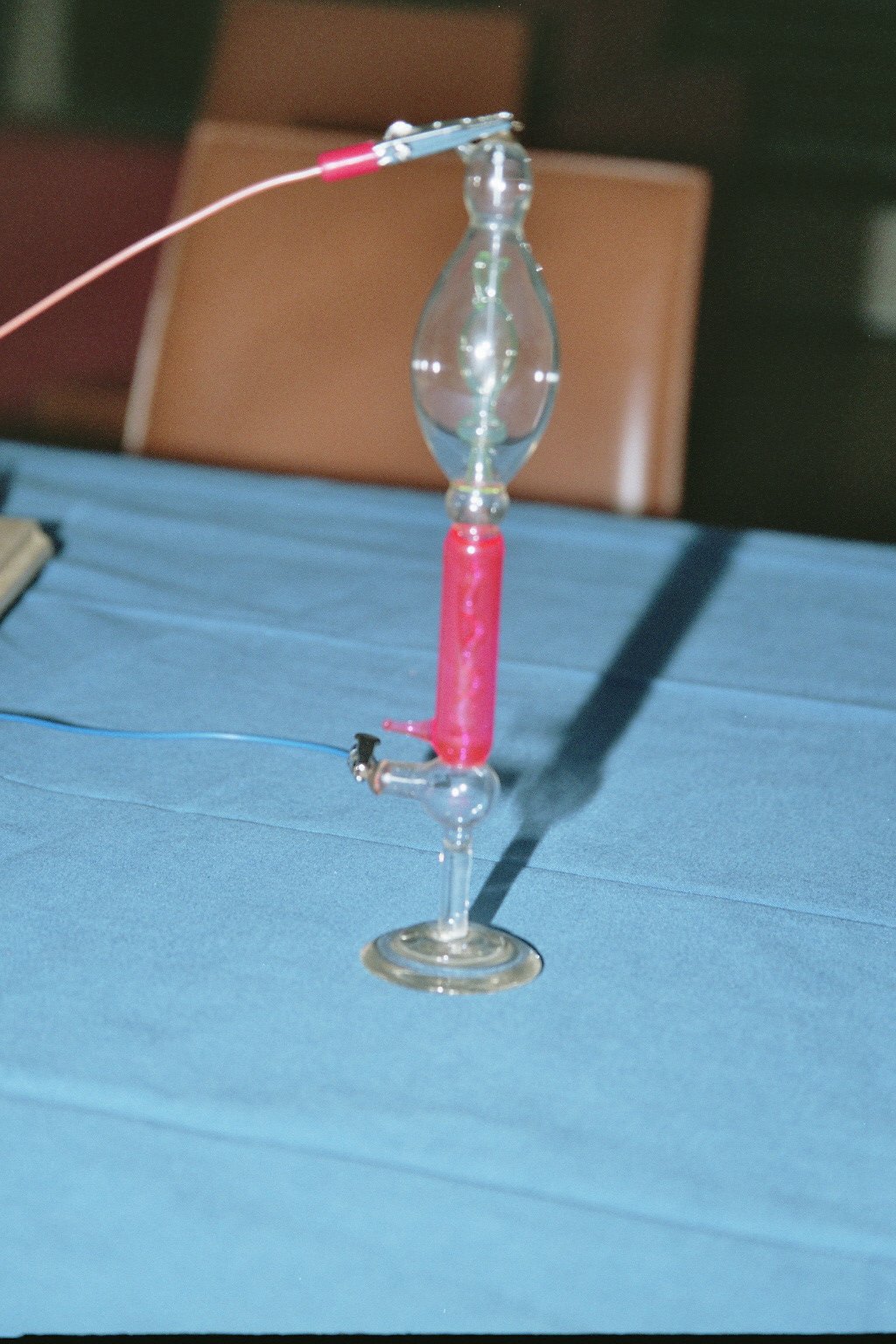
Here we have a really nice tube decorated with a target in the shape of flowers and leaves between the electrodes. This target is coated with fluorescent material that makes it glow red, blue and green. A uranium glass envelope adds a global green glow. It's interesting to remark that the target only glows when the negative pole of the generator is connected to the top electrode (watch the position of the black alligator clip to see the difference). When electrons come from the top and fall down on the target, the target glows and a shadow is projected on the uranium glass underneath . If electrons are coming from the bottom electrode, they strike the target on the uncoated side and there is no glow.
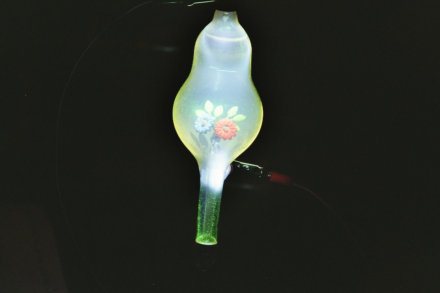
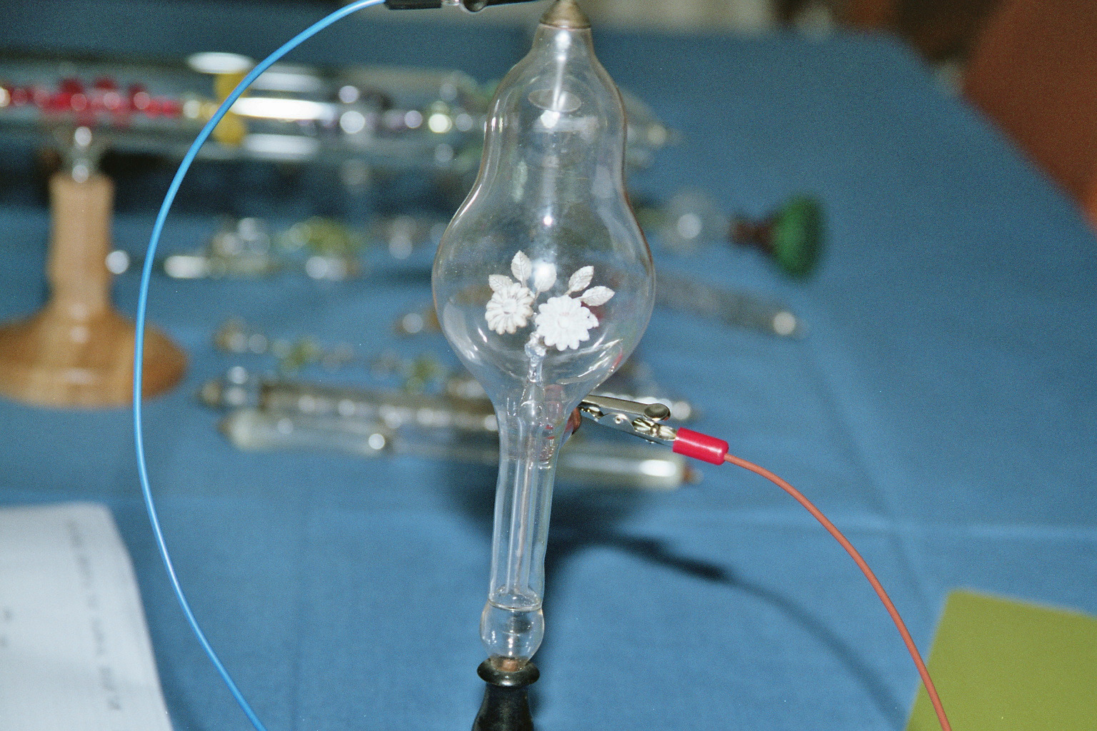
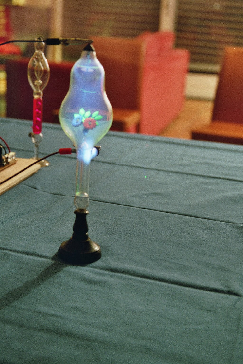
Tube with a flower shaped fluorescent target. Beware of polarity to make it glow by watching the position of the black alligator clip (click to enlarge).
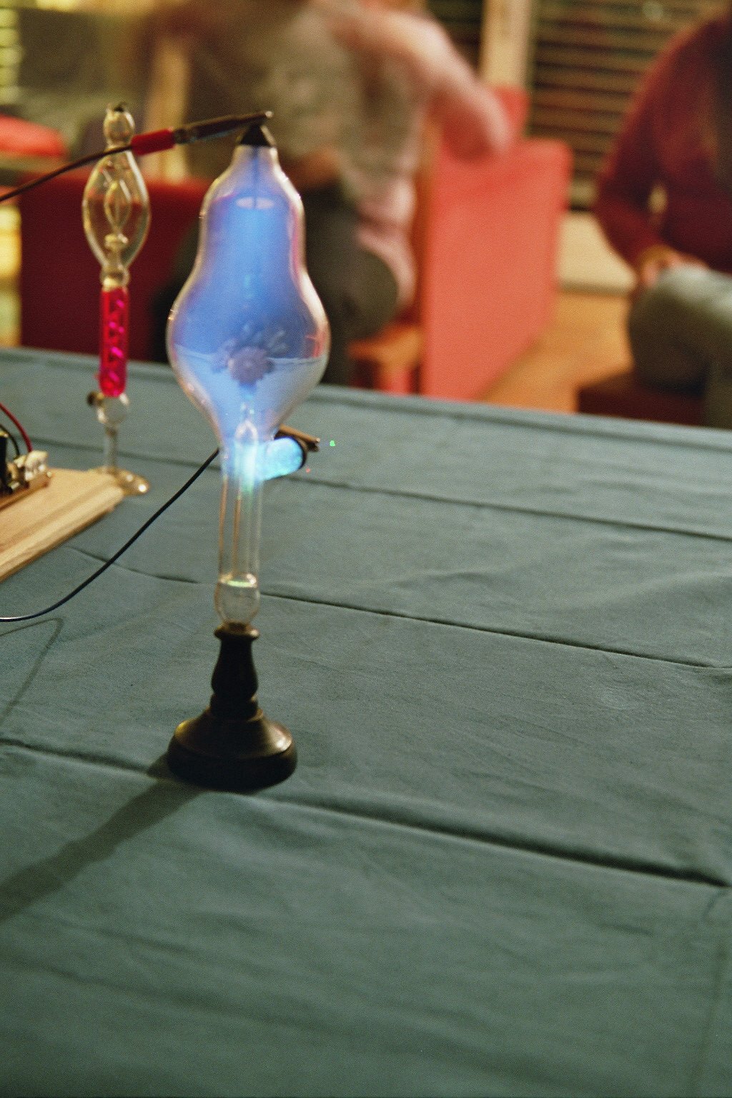
Here is another very special tube made of uranium glass. It has a propeller shaped target between the electrodes. When currents flows in the tube the propeller spins! It's unbelievable how tiny ions and electrons can generate a force large enough to make the propeller move.
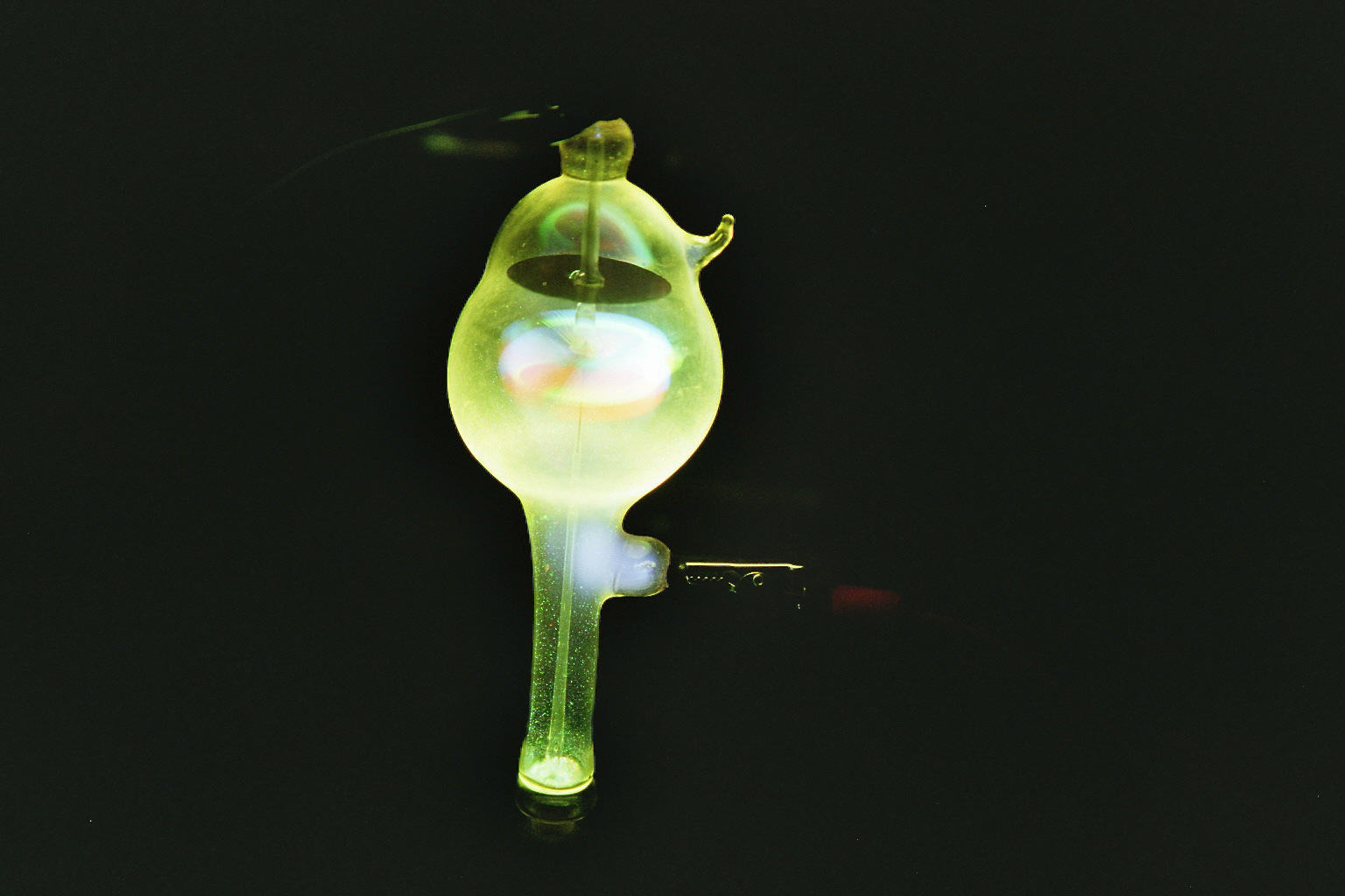
Special tube with a propeller shaped target between the electrodes. Te current makes the propeller spin (click to enlarge).
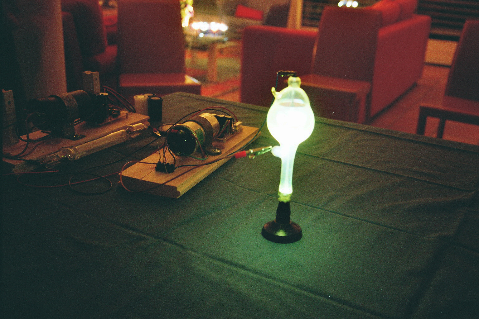
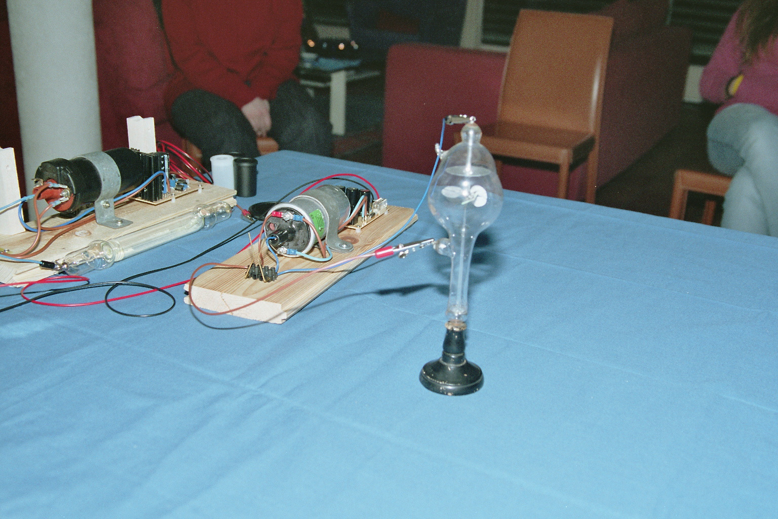
Finally a view of all the equipment used. All the Geissler tubes are in the middle: they are all one century old except the straight yellow one on the right which we bought new for testing. Than, the original Ruhmkorff coil is in the top middle part of the picture while the new high voltage generator is on the left. On the top a very crude 12 V power supply. Almost all the tubes worked except one that didn't strike.
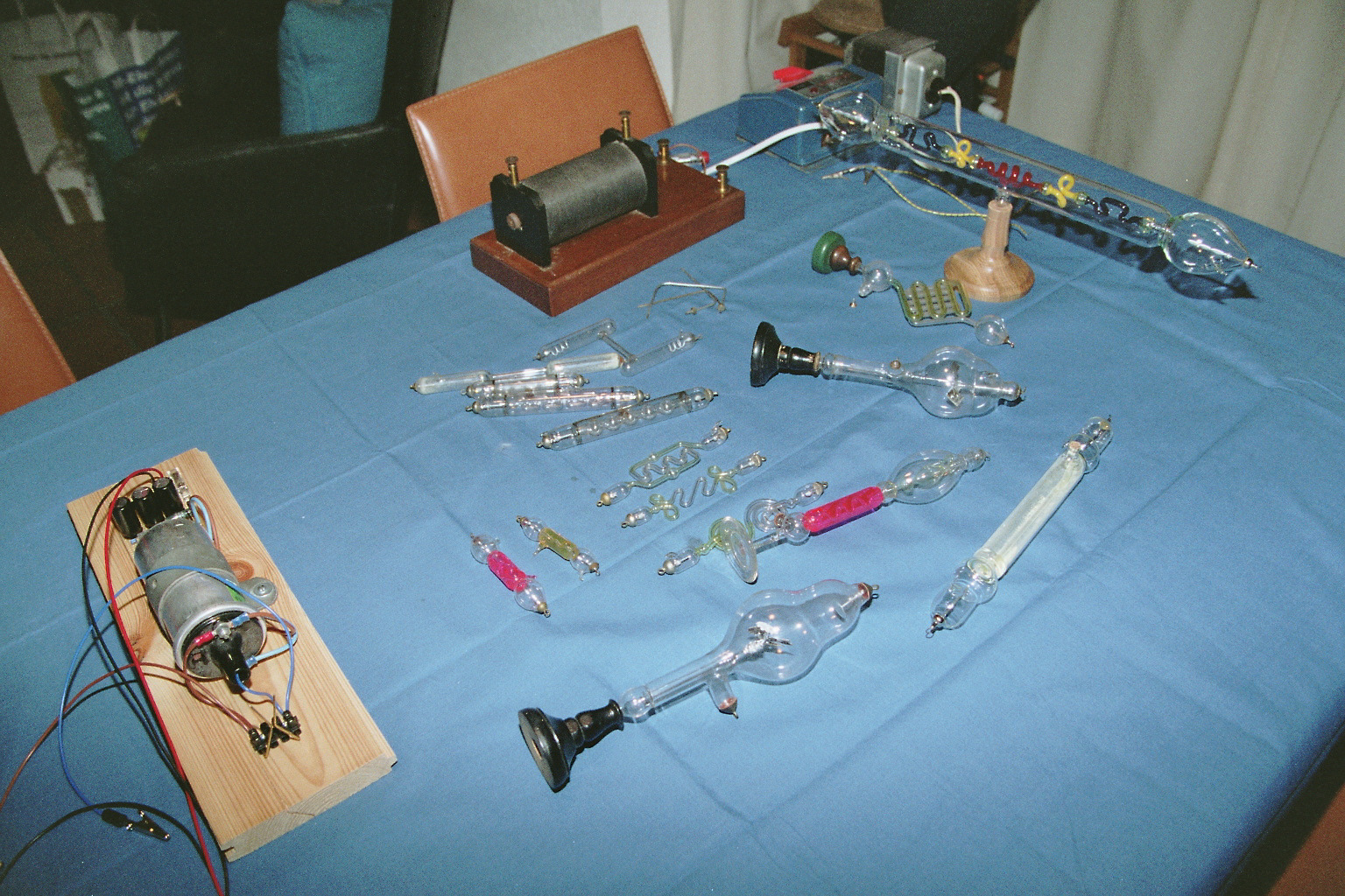
Global view of all the tubes, the Ruhmkorff coil and the high voltage power supply (click to enlarge).
Playing with Geissler tubes is very funny. One has to be careful with the high voltage, but seeing these tubes glowing in the dark is really beautiful. Having the chance of playing with vintage tubes is even better because its adds a nostalgic feeling about a past era where inventors could play at home with common materials (if we assume that blowing glass is common) and end up with awesome new objects. I strongly regret that I don't have a grandfather that made Geissler tubes and that I had to give back to my friend his precious collection...
| Home | Electronics | Page hits: 040522 | Created: 10.2012 | Last update: 05.2016 |