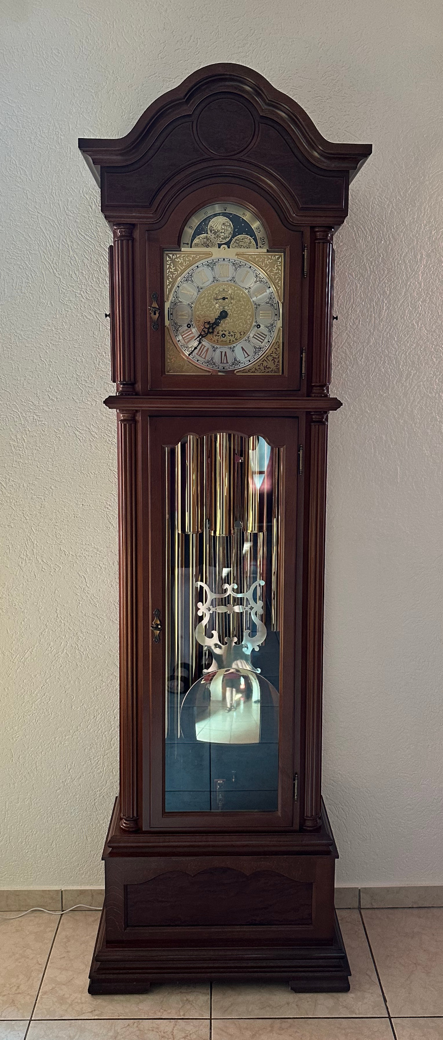
The grandfather's clock I modified to synchronize on GPS pulses. (click to enlarge)
I always had a fascination with clocks, all kind of clocks: electronic clocks and of course mechanical clocks. Mechanical clocks are a world on their own. They look simple and complex at the same time. You can work out how they work if you look at them long enough, but their design is far from simple. There is a hidden beauty in how those mechanisms can achieve complex functions like calculating moon phases, chimes, carillons while telling accurate time with "just" a bunch of gears and the power of a weight suspended on a thin chain.
As one would expect, in my living room there is a nice grandfather's clock. It's not a vintage clock; it's a modern one, built in 2004. It's a wonderful piece of German engineering with a very nice mechanism with plenty of bells and whistles such as chime and carillon.
The grandfather's clock I modified to synchronize on GPS pulses. (click to enlarge)
For what it is, it's fairly accurate, too; but to modern standards its accuracy leaves a lot to be desired. I once decided to adjust it right and after a lot of fiddling I could get it to run within about one minute per month. But this didn't last long, maybe 4 months, maybe half a year, than temperature changes and aging made it drift a bit and ended up with an accuracy of about 3 to 4 minutes per month. This is still a good performance for a mechanical clock, but today we are used to clocks that do much better than that.
Nowadays we can now buy extremely cheap GPS receivers that have a dedicated pulse per second (PPS) output with outstanding precision. "I wonder how hard it can be to run my grandfather's clock on a GPS..." I said to myself. And the answer turned out to be that it's fairly easy. This is how I did it.
It's actually quite surprising the amount of accuracy required to measure time. I mean measuring time for everyday living, not for special fancy laboratory applications. Let's compare it with measuring lengths. Imagine for a moment that you are measuring the width of a table with a ruler or a meter stick. You'll measure about one meter with an accuracy of about one millimeter. That's 0.1% and for that purpose is perfectly fine. If your clock, however, had an accuracy of 0.1% it would drift by about one and a half minutes per day and, after a month, it would be 45 minutes off: definitely unacceptable. A common quartz wristwatch will drift, say, 5 seconds per month. That is 0.0002% or 2ppm (parts per million). Compared to the length measurement before, this is like a 2 millimeter error over a kilometer. Good wristwatches can even do better. It's surprising, bit this is how it is: clocks must be accurate.
And talking about quartz crystals, not all crystals are good for a clock. For example, a common CPU-grade crystal has an accuracy of about 20 to 50ppm: not good enough to make a good clock. Here I'm talking about common crystals with frequencies in the 1.8MHz to 20MHz range in HC-49 housing. Better crystals exist, of course, at a higher cost. Or one can add a trimmer capacitor and manually fine tune it every once in a while to compensate for crystal aging. Even 32.768kHz crystals that are specifically designed for clock applications can be found from good under 1ppm models to really bad 100ppm ones. In all cases, even with a good crystal, the oscillator circuit must be very well engineered to keep the accuracy as a drive level a bit too strong or a capacitor with the bad temperature coefficient can easily waste the precision of the crystal. But I digress: this page is about mechanical clocks...
Let's have a look at the picture below: can you guess which one is the most accurate instrument? Hint: it's not the micrometer.
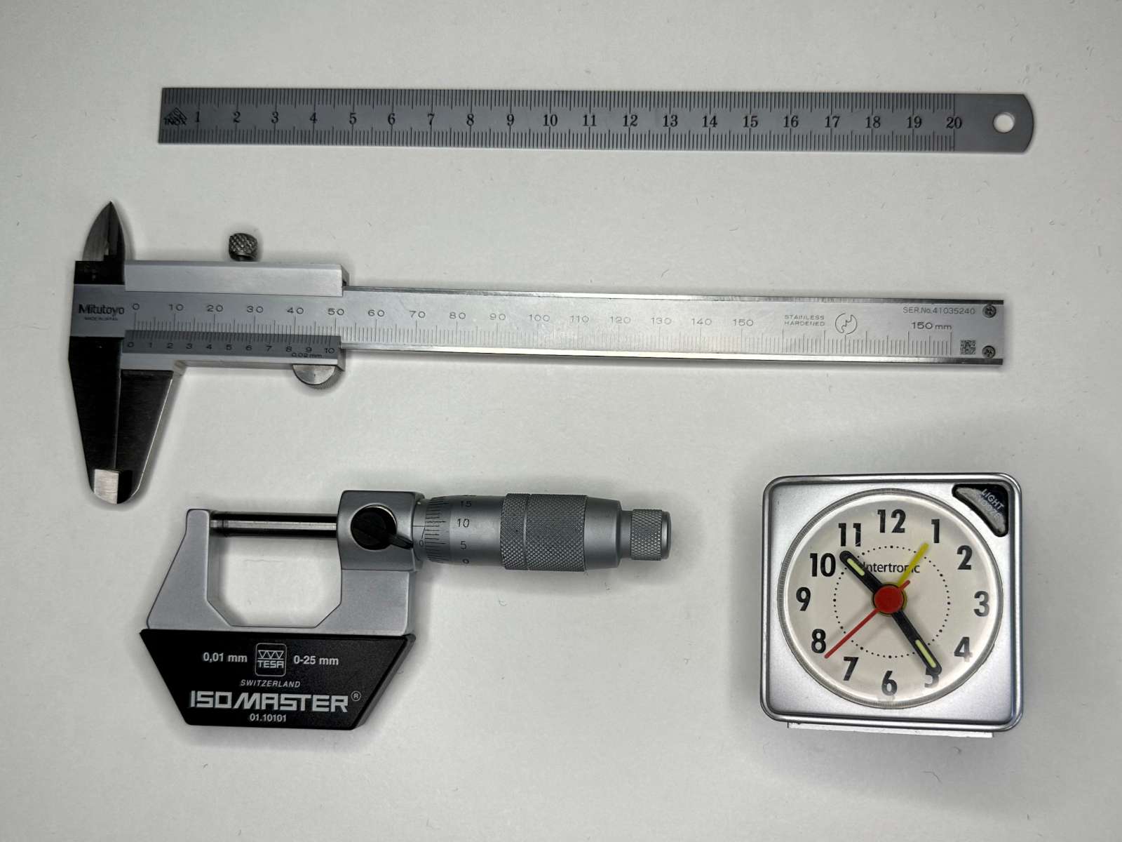
Can you guess which one of these instruments is the most precise?
Hint: it's not the micrometer. (click to enlarge)
Well, let's see. The steel ruler has millimeter marks, so our best guess will be, say, 0.25mm over a length of 200mm. This is a precision of 0.125% or 1’250ppm.
The caliper has a Vernier scale that allows appreciating 0.02mm over 150mm. It does about 10 times better than the ruler with only 133ppm.
The micrometer is even better. It has 0.01mm marks and we can appreciate, say, 0.0025mm (yes 2.5μm) increments between them, but it can only measure up to 25mm, so its overall precision is only 100ppm.
Finally we have the cheapest of the cheap alarm clocks. It's only good for 2s per day, but this is already 23ppm, four times better than the micrometer. Again, it's surprising how clocks must be accurate compared to other instruments.
It hasn't always been like that: a few centuries ago, the position of the sun in the sky was more than enough to tell the time and our life was not as dependent on time as it is today. Plus or minus a quarter of an hour wasn't a big deal. Well, it has to be said that the sun defines the day, so even if the observation of its position on a sundial is hard to get accurate, it never drifts. But things changed when trains become popular in the middle of the 19th century. If you're even one minute too late your train is missed. This actually generated a lot of new problems for measuring time that needed to be solved. Until then, every town determined its time by observing the sun and setting noon when the sun was at its highest point. But this depends on where you are, on your longitude. For every degree of longitude the local time changes by 4 minutes. And where I live, at a latitude of 46°N, for every 19km you travel East or West, the local time changes by about one minute. By the way, you can easily calculate how far you have to travel East or West for the local time to change by one minute with the following formula, where Re is the radius of the earth and Lat is the latitude:

So, when trains become popular, measuring accurate time started to become a problem. Which time should one use? The one of the departing station? Or the one at the arrival station? And what about in-between? So in the middle of the 19th century train companies started defining standard times, generally based on the local time of the city where they had their headquarters or the capital of the state/kingdom they were operating.[1] But even this, quickly ended up in a mess.
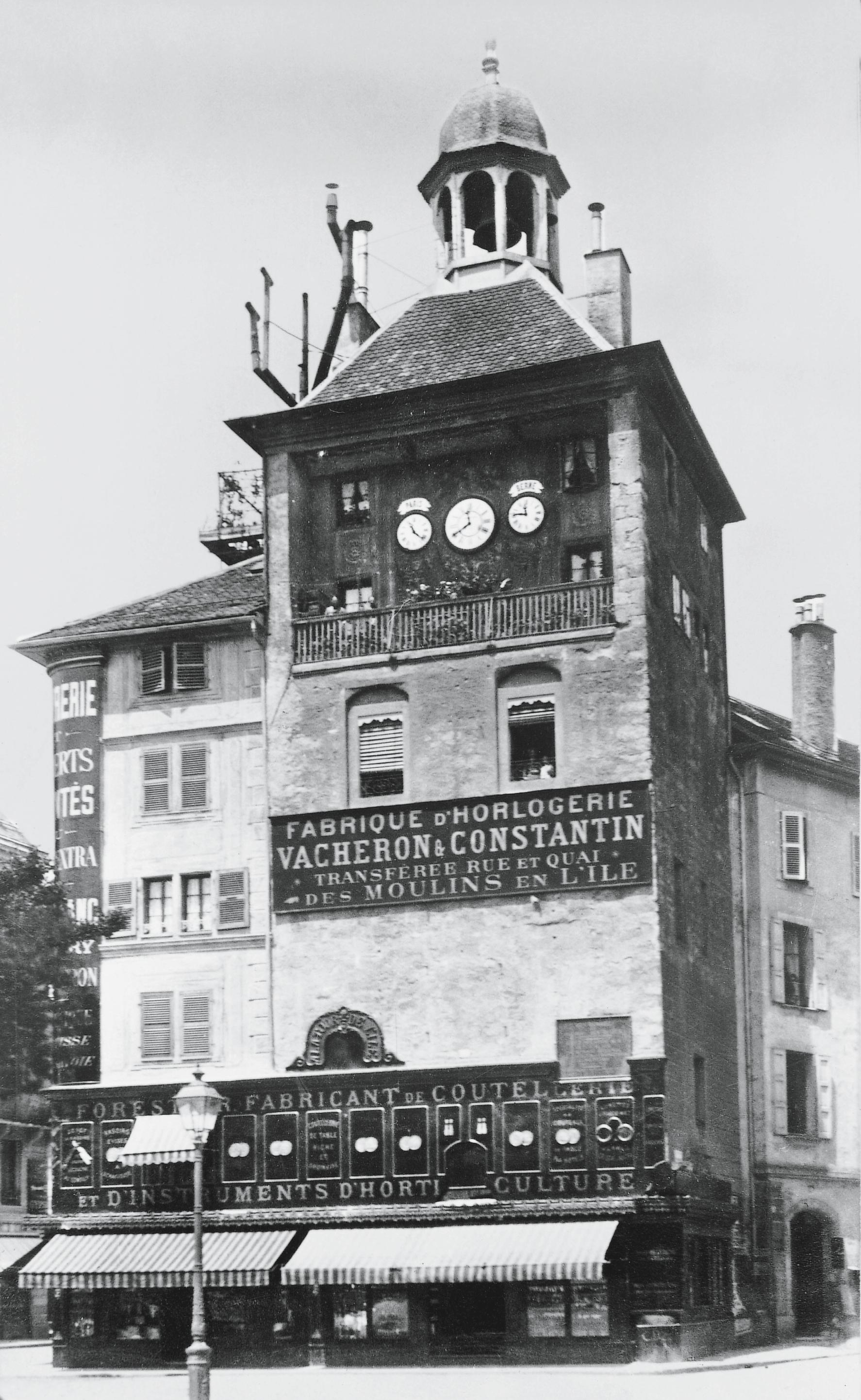
A example testifying about this problem could be seen in the Tour de l'Ile in Geneva (literally "the Island's Tower") that had three clocks: a big one to show the local time in Geneva (longitude 6.14°E), a smaller one to the right to show the time in Bern (7.44°E) that is 5 minutes and 12 seconds ahead, and another small one to the left to show the time in Paris (2.30°E) that is 15 minutes and 23 seconds behind. This tower that at that time was the house of a famous Swiss watchmaker factory had these three clocks until 1886.[1]

Let's take another example: imagine you lived in, say, 1850 and wanted to travel around the Konstanz lake, which is right in the middle of Europe. Let's also imagine that you were lucky enough to own a watch, maybe a pocket watch that was common in that era. Say you started from the city of Konstanz that at that time was part of Grand Duchy of Baden and used Karlsruhe time (longitude 8.40°E). If you turned clockwise, 73km later you arrived in Friedrichshafen in the Kingdom of Württemberg that used Stuttgart time (9.18°E); so not only you had to show your passport but also had to adjust your clock forward by 3 minutes and 07 seconds. Then you traveled another 28km and arrived in Lindau in the Kingdom of Bavaria and you had to adjust your clock to Munich time (11.58°E) by moving it forward by another 9 minutes and 36 seconds. 10km later you’re in Bregenz in the Austrian Empire and used Vienna time (16.37°E): another clock adjustment of 19 minutes and 10 seconds in the same direction. But after another 26km you arrived in Rorschach, Switzerland, that used Bern time (7.44°E): now you had to adjust your clock in the other direction by 35 minutes and 43 seconds. When you finally got back to Konstanz after another 40km you had to adjust it forward a final time by 3 minutes and 50 seconds. If you're not familiar with the region, this is not a big trip: it's about 170km in total and about a 3 hours drive on modern roads (say 4 hours with modern traffic jams). Even today, it takes you through three countries: Germany, Austria and Switzerland but now everywhere is in the same time zone and no fancy clock adjustments are needed anymore.[1]
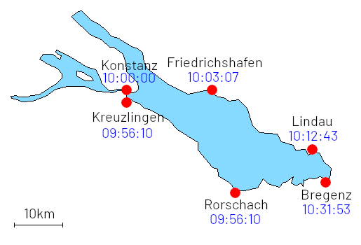
A simplified map of the Konstanz Lake with a 10km reference distance
for scale and indicating the local time in the different cities around 1850
when in Konstanz is 10:00:00.
This gives an idea of how messy measuring time was back then. Another curious fact is that in this period the railways took over the church in defining the time: the reference everybody used moved from the clock on the church bell tower to the clock at the train station.[1]
Defining a standard time for a whole region brought the problem of keeping all the clocks synchronized; they must all tick at the same time. At the beginning there were railways employees in charge of traveling with an accurate watch to manually and periodically synchronize the clocks at the different train stations. The telegraph was also used but electrically synchronized clocks become available around 1870 and quickly replaced the previous methods.[1]
The idea of dividing the world in 24 time zones exactly one hour apart started to spread in 1876 thanks to Sandford Fleming who strongly advocated this system at several international conferences, but it took until 1884 until (almost) everybody agreed on where the 0° meridian should be. It was set to be the one going through the observatory of Greenwich at the "international prime meridian conference" in Washington that year. By the end of the century almost all European and North American countries were using time zones.[1]
In many countries institutes were created to define a precise national time and distribute it across their respective countries. Broadcast radio station transmitted precise time signals several times per day to allow people to synchronize their watches. I remember adjusting my wristwatch or the clock in my car for years based on those beeps heard on the radio. With the advent of digital radio in recent years, there is disturbing a delay of a few seconds in the transmission, probably due to buffering, I guess, making these beep-beep-beeeeeeeep much less accurate than they used to be.
Then radio controlled clocks become popular in the '80s and '90s. Here, in central Europe many clocks are still synchronized today on the German long-wave transmitter DCF77 that started broadcasting precise time signals in 1973.[1] Now many devices synchronize their clock over the internet. Maybe one day long-wave time stations will be replaced by internet time, the future will tell. For example the Swiss time station transmitter HBG was shut down in 2011.
The beauty of synchronized clock is that they all tick at the same time and you don't need to adjust their pace anymore. We are so used to see all clocks synchronized that if one is out, even by only a few seconds, it looks odd. It looks as if it has a problem.
So I had to do something for my grandfather's clock. I had enough of moving its hands a few minutes forward or backwards every time I winded up the weights. I wanted it to be synchronous as well. Because pendulums are notorious to synchronize to each other even if you don't want to, it shouldn't be too hard to do; or is it?
The problem of synchronizing clocks over a wide region has already been solved and there are many different ways to do it. The prototype of the first electric clocks was built by Alexander Bain in 1840 and patented in 1841. But they become popular around 1870.[1] Here I give some examples that I have considered for this project with their pros and cons.
One solution is to have a master clock that distributes a synchronization signal to all slave clocks. This signal, in our case, would the PPS from the GPS. All slave clocks are electromechanically driven by this signal that makes them tick through an electromagnet or a stepper motor. This is what was used, for example, by the legendary Favag clocks used in many factories to indicate the beginning and the end of the shifts. But implementing this concept in my grandfather's clocks would mean removing the pendulum and replacing it with an electromechanical actuator to "brute force" the escapement and make the clock tick. I don't like this solution because there are a few drawbacks which are an absolute no-go for me: removing or stopping the pendulum is esthetically unpleasing and would completely ruin the nature and the aesthetics of the clock. I love seeing it swing and click. The noise would also be different and probably less pleasing than the gentle tick-tock of the escapement mechanism; I fear it will sound like the blinker in my car... Another drawback is that if the PPS signal is lost, by a power outage for example, the clock would stop. I don't want to transform a mechanical clock into an electrical one ruining the nature of the clock even more. I want it to be still powered by its weights and I want it to keep ticking even when there is no electrical power, like mechanical clocks do. Then, mechanically speaking, it's a lot of work to modify the escapement. And playing with the escapement is really fiddly. So, this solution was immediately discarded. I want to keep the modifications to a minimum and I want to be able to easily revert it back to a pure mechanical clock.
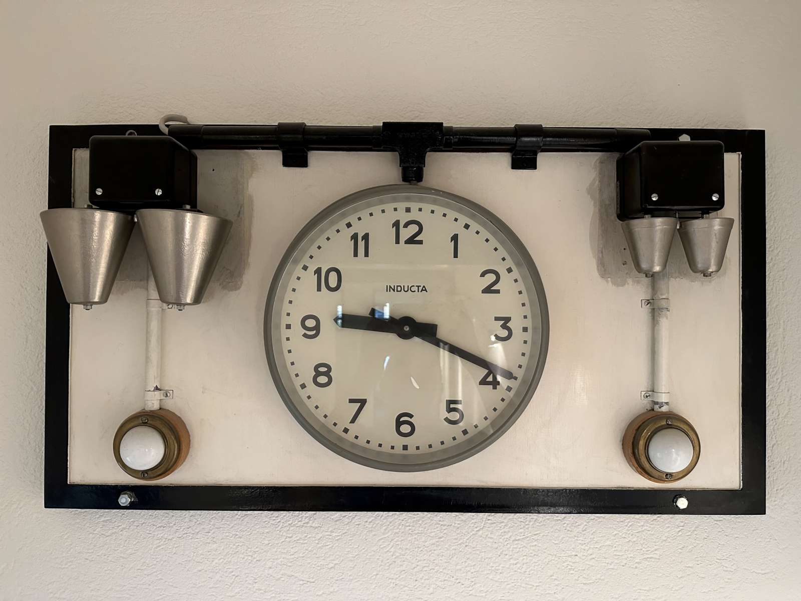
A nice industrial salve clock that ticks with pulses made by Inducta
in the '60s to regulate working hours in a factory.
(click to enlarge)
Another solution is to run the pendulum considerably faster and count the swings of the bob. Then, when the clock has counted a minute the pendulum is stopped until exactly a minute has elapsed and let it go again. The pendulum can be stopped, for example, with an electromagnet when it's at its maximum amplitude. I've seen this system in use in many church clock towers and, for example, in the castle of Burgdorf (Switzerland) as well.[7] This solution has many drawbacks, too. The electronics to control the pendulum is more involved as it has to detect the position of the pendulum and catch it at the right time, count the swings and keep track of the correct time. Mechanically is also quite complicated and intrusive to the clock. But there are two bigger problems: first the frequent pauses would make the clock unpleasant to watch, unpleasant to hear and almost feel broken. It's ok in a clock tower where nobody sees the bob swinging or hears the escapement ticking, but in my living room is a big no-no. And the second problem is that without the PPS pulses the clock would drift very quickly off the correct time; something like one hour per day... So, this solution has been immediately discarded, too.
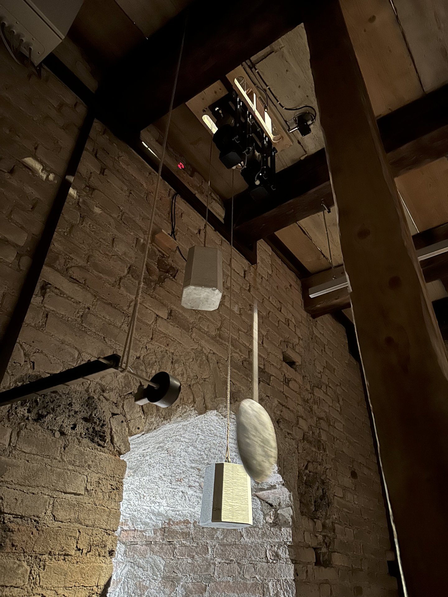
The synchronization system of the clock of the Castle of Burgdorf.
Please note the pendulum sensor at the top and the electromagnetic pendulum
catch system on the left. (click to enlarge)
A similar system is the one that was used by the iconic Swiss Railways clocks manufactured by the company Moser-Baer since 1947 [7] where the second hands completes a minutes in about 58 seconds and then waits for a minute synchronization signal. When the signals arrives the minute hands advances by one minute and the seconds hand starts spinning again. Here there is no escapement; just a motor geared up to run faster than the minute. I remember being puzzled by the behavior of these clocks already when I was a kid and I even asked a railway man why it stopped every minute and he replied "it waits for a signal from Bern"... By the way, this is how vintage Swiss Railways clock used to work, because recent models use modern technology such as GPS or NTP and only mimic the old behavior of the seconds hand.[8] Applying this solution to my grandfather's clock has all the drawbacks of the previous one, but would also require major and irreversible mechanical changes to the mechanism. Again, this is not at all the way to go for me.
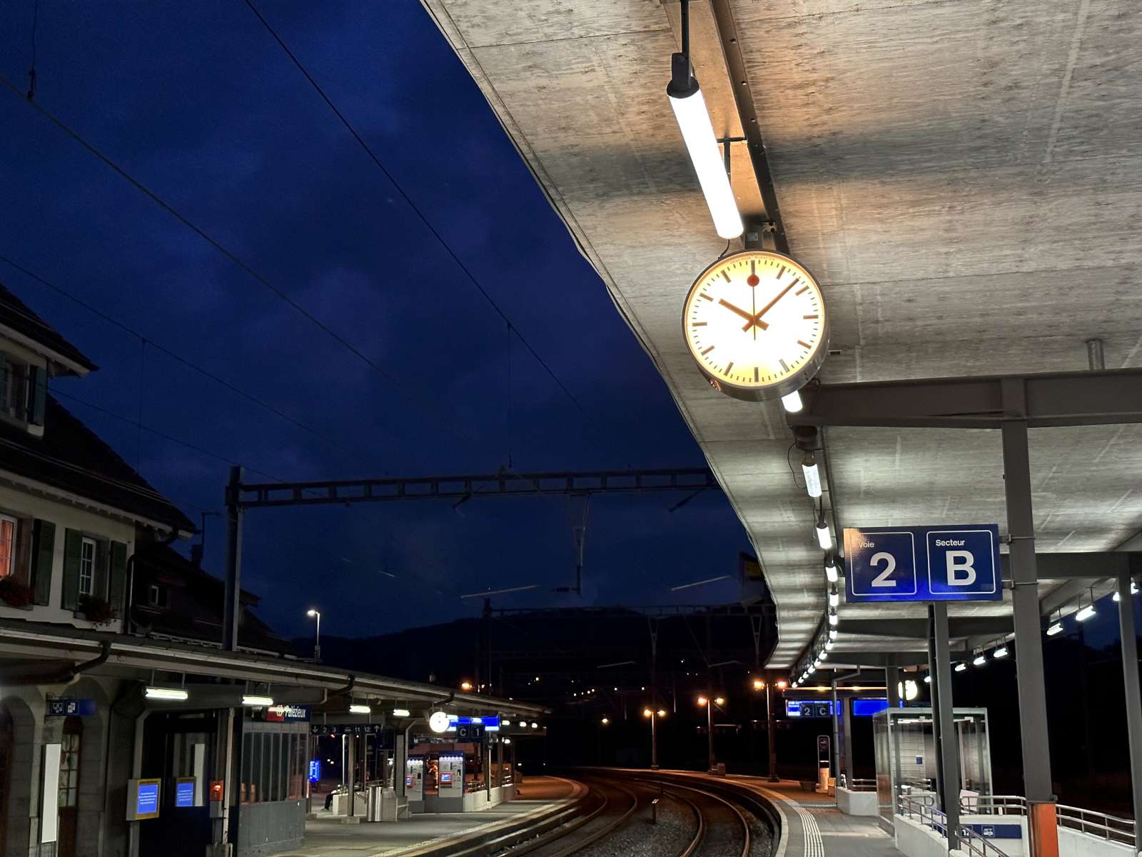
The iconic Swiss Railway clock present in all Swiss train stations completes each minute a little faster and then waits for a synchronization signal. (click to enlarge)
But a pendulum is a mechanical resonator. It's the mechanical equivalent of the LC tank circuit. Like all resonators it has a resonant frequency. In a mechanical clock the escapement "tickles" the resonator and provides the extra energy needed to compensate for the losses and keep the amplitude of the oscillations. But every resonator can also be excited with an external signal. If the frequency is very close to its resonance it will be forced to oscillate at that particular frequency, like connecting an LC tank to a signal generator. So this is the idea: find a way to excite the pendulum with the PPS signal so that it's forced to oscillate at exactly the right frequency and the clock will run correctly. Like all resonators, the coupling of the signal must be very weak, otherwise its resonance is destroyed. This solution, if it works, has many advantages. First it's not intrusive with the existing clock mechanism. The clock keeps ticking with the exact same escapement mechanism and the same sound. If the PPS signal is lost the clock will keep ticking on its own with its own precision until the signal comes back, keeping it a mechanical clock. And finally the electronic circuit is very simple. So, this is the solution I will try.
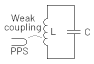
LC equivalent of the proposed solution.
Almost all grandfathers' clocks, I mean column clocks that stands on the floor, use a pendulum that is about 1m long because of their large size. It's actually 995mm long, from its fulcrum to its center of mass. This gives a very convenient period of 2 seconds. One second to swing in one direction, tick, one second in the other direction, tock, again and again. This frequency can easily divided down with simple gears to count minutes, hours, days, weeks, months,... This is why almost if not all floor standing clocks are like that. This is ideal for synchronizing with one pulse per second.
The period of a simple pendulum is given by:[2]

This is only a first order approximation but for our purposes it's good enough. Knowing the period T (2 seconds) and the acceleration due to gravity g (about 9.81m/s2) we can find L:

We can also calculate how much the period will change by slightly adjusting its length. This can be evaluated by taking the derivative of T with respect to L:
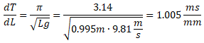
This in other terms, this means that making the pendulum 1mm shorter or longer will change its period by shorter or longer by 1.005ms and make the clock faster or slower by 43.4 seconds per day. My clock has a knurled nut below the bob with an M3 thread. Its half of a millimeter pitch will adjust the clock by half of that amount (21.7s) for every turn of the nut. And this is a good to know when making adjustments: you get much quicker to a correct adjustment if you can determine by how much you have to turn the nut then by doing it by trial and error.
Pendulums are known for willing to synchronize to other pendulums all by themselves, even when you don't want to. This was discovered by Christiaan Huygens already in 1665 with two close-by pendulum clocks and he called that "the sympathy of two clocks".[3] This is not surprising, all resonant structures have a tendency to pick up small signals if they are close to their natural frequency and amplify them; this is what resonance is all about. The question is more on how to "tickle" the pendulum with the correct frequency.
The first idea was to install a little mass on a small motor placed somewhere inside the clock housing to transfer its vibrations and drive it with the pulse per second signal. This would reproduce the original Huygens experiment and should work. But it would be noisy and use quite some energy.
Another idea is to use an electromagnet and apply a tiny force at the correct frequency on the pendulum itself. But where should we place the electromagnet? At the edge of the oscillation movement where the bob stops, to the far right or to the far left? Or at the bottom dead center of the pendulum where the speed is greater?
I think all these ideas could work, but I decided to start with the last one, just because it seems the easier to do. I said to myself: "if that doesn't work, I'll try the others..." but that worked fine on the first try.
The idea here is that every time the bob passes close to the electromagnet a force is applied. If the pendulum is too fast the pulse will arrive when the bob is already past the electromagnet and will retain it slowing it down. If the pendulum is too slow the pulse will arrive while the bob is still approaching the electromagnet, attracting it and speeding it up. If the pulse and the bob are too far apart, nothing will happen until the bob is within the reach of the electromagnet when the pulse arrives, but it's just a matter of time until this happens.
Before an electromagnet can be used I needed to add some iron to the pendulum bob: it's made of brass and it's not ferromagnetic. Now, how big should this piece be? I have some Ø20mm round stock lying around that would be perfect for this modification, but before I start machining a quick check is a must.
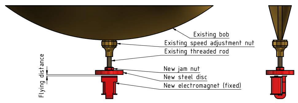
Position of the electromagnet below the pendulum bob.
Let’s start by evaluating the pendulum speed. The angular position of the pendulum as a function of time t is given by:[2]
.png)
Where θ0 is the angular amplitude, T is the period and φ is the phase. We can find the angular velocity just by taking its derivative:
.png)
We set φ=0 so that θ(t=0) is also 0 and our calculations are easier. We don't need to worry about the phase for this purpose. I measured the full amplitude 2x0 of the oscillation with a simple ruler and turned out to be about 100mm, 50mm in each direction. By the way, in horology the amplitude x0 is defined from the bottom dead center to the maximum swing.[6]
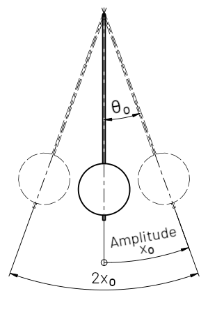
Amplitude and angles of a pendulum.
From them linear amplitude we can find the angular amplitude θ0 using:

We can now compute the angular speed at the bottom dead center, where θ=0, for example when t=0:
.png)
And finally convert the angular into tangential speed:
.png)
We can now calculate how long it takes to travel 20mm, the diameter of the metal disc under the bob:
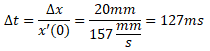
The GPS receiver I have on hand provides 100ms pulses, and from what we just calculated, it's almost the ideal pulse width. At this stage we don't need a perfect match; we just want to avoid the situation where the pulse width and the travel time are orders of magnitude off. So a Ø20mm steel disk is reasonable to synchronize the pendulum with 100ms pulses.
From that mild steel bar I made a Ø20mm 3mm thick disk. The thickness was just a convenient value for tapping, but it has no reason to be exactly 3mm. Thicker is heavier so it shouldn't be too thick. But if it's not thick enough it's hard to tap reliable threads. I could have removed some steel off the upper face while keeping the lower face flat, but I didn't bother as I was confident I could easily readjust the bob for this added mass. And I could.
I drilled the center and tapped the hole M3×0.5mm so that it could be threaded directly to the rod at the bottom of the pendulum, right below the speed adjustment nut. As for good watchmaking practice, I sanded smooth the surface, polished it and blued the part so that it looks good.
I then installed the disk under the bob and blocked it with an M3 brass jam nut. This immediately slowed down the clock by several minutes per day. So I spend the next few weeks to re-adjust it until it run within 1 minute per month again.
For the electromagnet I chose to pry open an old 5VDC relay and see if I can salvage the coil and maybe the magnetic core. After destroying a few relays I found one that works. The coil inside is placed horizontally and has a C-shaped iron core that is very convenient for this application because the poles are well within the Ø20mm disc. The 5VDC rating is perfect for using with a 5V USB power supply. And if it can attract the contacts of a relay, it can definitely apply a significant force to the pendulum. This relay has a DC resistance of about 100Ω so it only draws 50mA.
I added an LED (LD1) to the electromagnet so that by simply looking at the pendulum one can easily see if the bob is synchronized to the flashing of the LED or not. And of course I included a flywheel (flayback) diode (D2) to get rid of the voltage spike generated by the inductance of the electromagnet coil (L1). I mounted everything on a little PCB so that it can be easily mounted on a support and its position adjusted.
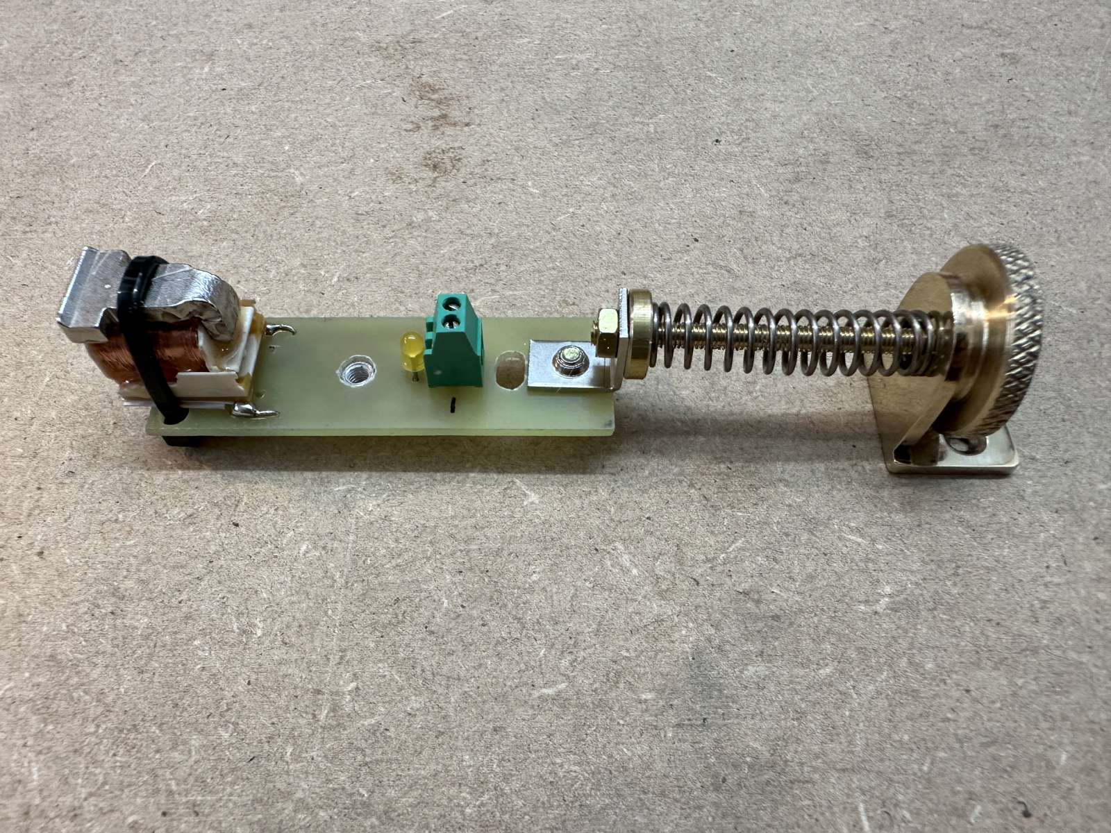
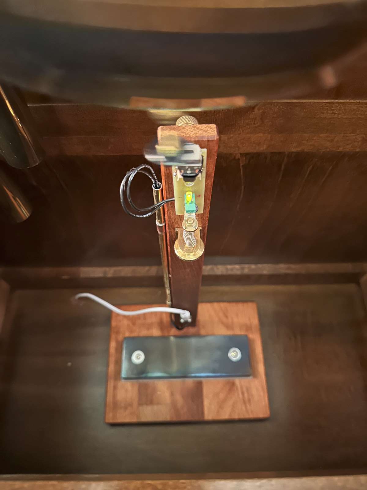
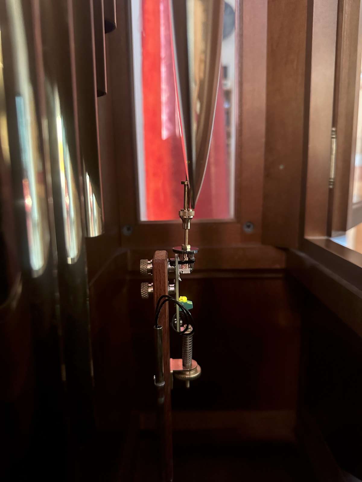
The electromagnet on his support PCB, the LED and the fine-pitch screw to adjust its position. (click to enlarge)
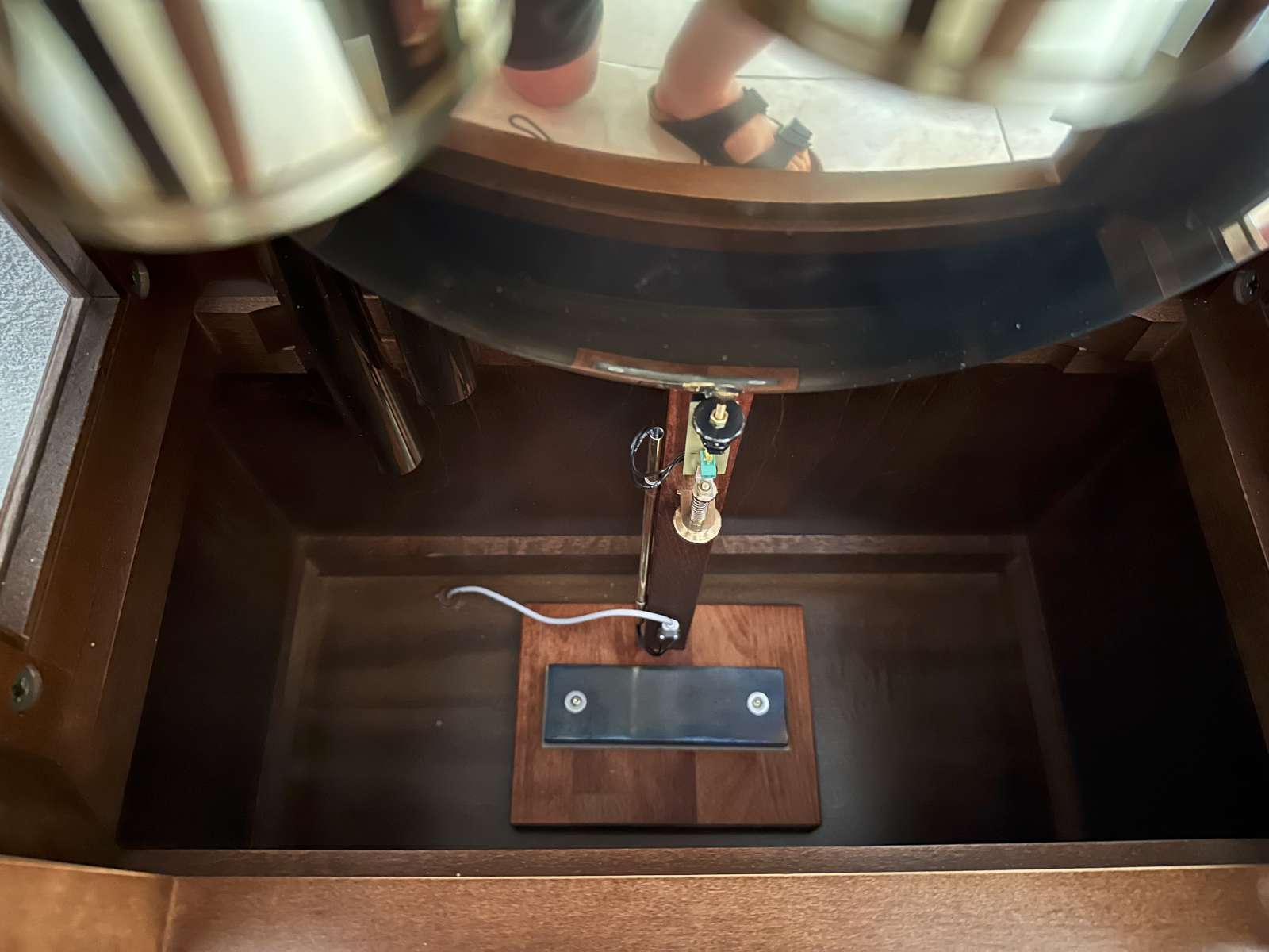
I wanted to minimize the modifications to my grandfather's clock, so I built a support that simply sits in its basement. It's a flat base with a vertical arm made of hardwood that I stained to match the clock housing. To keep it in place without screwing it to the clock base, I added a weight in the form of a steel plate. I chose a piece of bar stock of suitable dimensions, cleaned it, sanded it, slightly polished it and hot blued it. It weighs a little shy of 1kg, but the exact value is not important, it just needs to be "heavy enough".
On the vertical arm I milled a slot to adjust the position of the electromagnet. In this kind of electromagnets the magnetic force decreases approximately as the inverse of the distance squared [4], so it must be placed very close to the bob and a fine adjustment is a must. I found out that adjusting the position by loosening the two screws, moving the electromagnet and tightening them again was actually pretty hard to do. So I made a second version with an adjustment screw, a large knurled wheel and spring to get rid of the play in the mechanism. This is much easier to adjust. I also used an M3×0.5mm threaded rod for its fine pitch. This turned out to be quite a lot of lathe work. But every part had to look nice and got some sanding and polishing. After all, it's a clock: mechanical parts must look good.
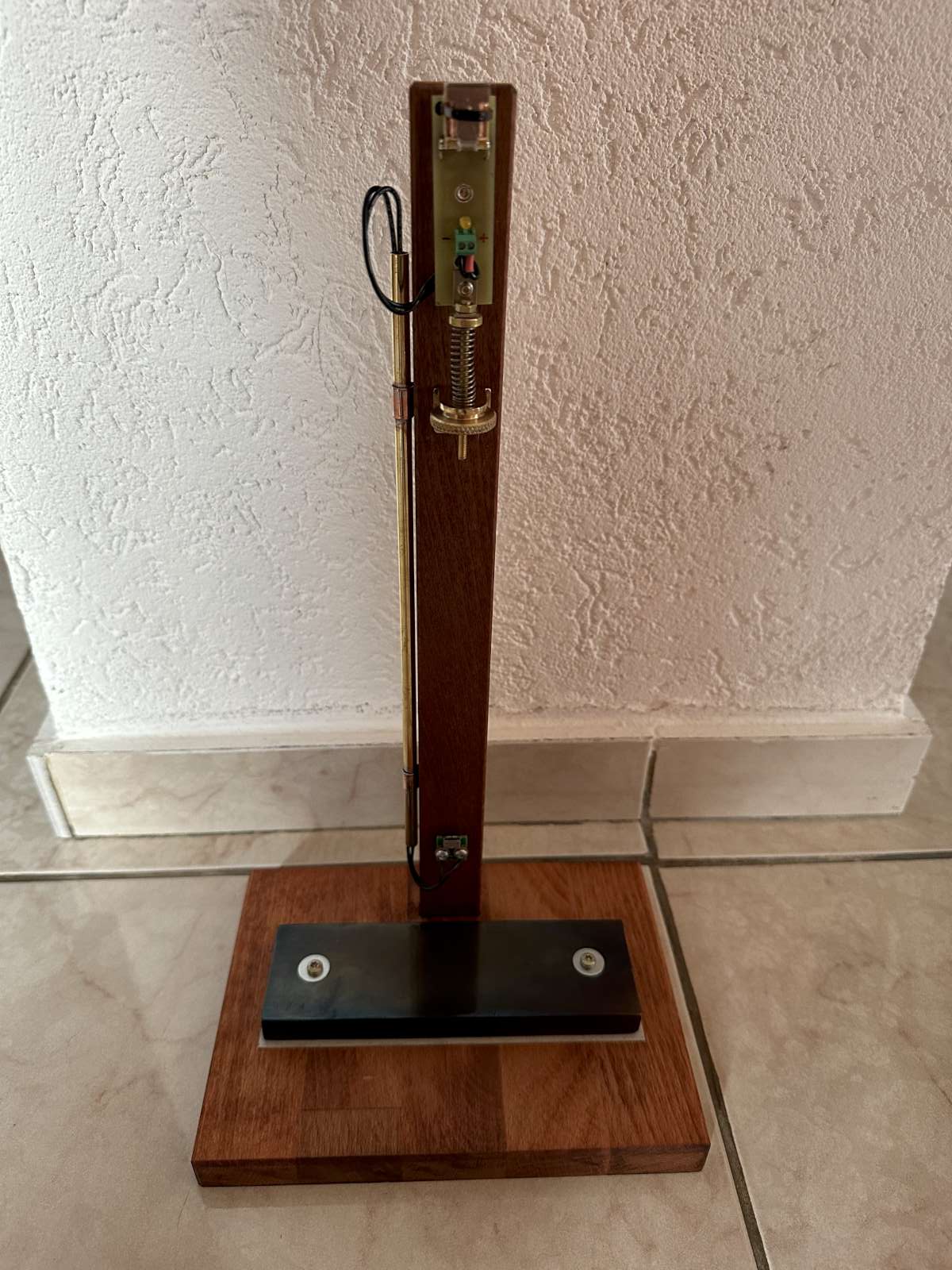
The wooden holder for the electromagnet complete with its weight to hold it in position. (click to enlarge)
As a GPS receiver I used a NEO-6 module board. The kind of module boards used to play with Arduinos or Raspberry Pis that can be imported for just a few bucks. It's basically a u-blox NEO-6 GPS receiver mounted on a tiny PCB with a voltage regulator and a few interface pins ready for a 2.54mm header. In terms of electronics, not much else is needed: just a MOSFET to drive the electromagnet and a few passive components. As MOSFET, for T1, I used a PMV31XN just because I have a plenty of those in my junk-box. Any other N channel MOSFET with a gate threshold voltage compatible with a 3.3V logic level will do the job. The one of the PMV31XN is between 0.35 and 1.8V. This MOSFET can also carry a current of 5.9A and has a maximum on-resistance of 53mΩ that are more than enough for a 50mA 100Ω electromagnet.
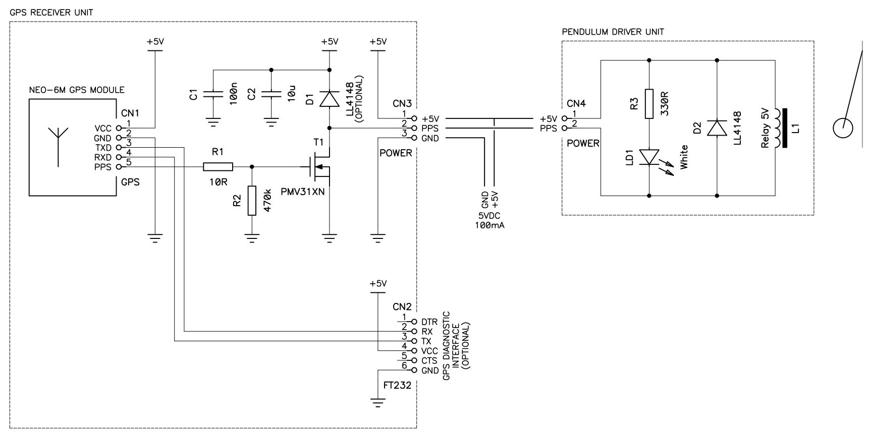
Schematics of this GPS pendulum synchronization circuit.
(click to enlarge)
The full schematic is available here: gps-pendulum-clock.pdf (18,593 bytes).
I included a flywheel (flyback) diode D1 here, but this is not really necessary as there is another one with the coil (D2). But it doesn't hurt. I actually started the design with D1 close to T1 thinking of having just that one, then I changed my mind and preferred to have the diode close to L1 for EMC reasons; so I added D2 and never bothered removing D1. By the way D1 and/or D2 are LL4148 that are only good for 100mA. The LL4148 is the SMD (MELF) equivalent of the famous 1N4148. They work perfectly for a 50mA electromagnet, but should be upgraded to a larger diode if the electromagnet draws more current than 100mA. Basically the flywheel diode must be rated for as much current as the inductor it works with.
The two resistors are there just for good practice, but aren't strictly needed. R2 makes sure T1 is in a known state if the PPS pin of the GPS is in a high impedance state, which can happen during startup. But even if this happens there are no consequences other than a stray pulse, so it could be omitted. Its value is not critical, anything between 10kΩ and 1MΩ will do. R1 makes sure T1 won't oscillate during the transitions. It's good practice to have it, but even without it, the circuit will probably work just fine. Again, the value is not critical, anything from a few Ohms to a few tens of Ohms will do, but it could be replaced with a short. The same can be said for the two ceramic capacitors C1 and C2: they are probably not needed as the GPS module should have its own decoupling, but one never knows... it's easy enough to include them and be sure the power supply is clean. The values are not critical, but at least the 100nF or so capacitor (C1) should be a ceramic one. The larger one (C2) can be a ceramic, electrolytic or tantalum capacitor of 10μF or more. It's just good practice to include them.
I also included a connector (CN2) for an FT232 serial to USB adapter to connect the GPS module to a PC to modify its settings. I thought it could be useful to reprogram the parameters of the pulse per second signal, for example to change its frequency or its length. It turned out it wasn't necessary as the default pulse works fine. This is actually good news because the NEO-6 has no non-volatile memory: if a different configuration would have been required I should have changed for a more powerful module (a NEO-6M or a NEO-8) or added a microcontroller to reconfigure it every time. But this is not necessary: the GPS works straight out of the box and requires no configuration. So CN2 can be omitted as well.
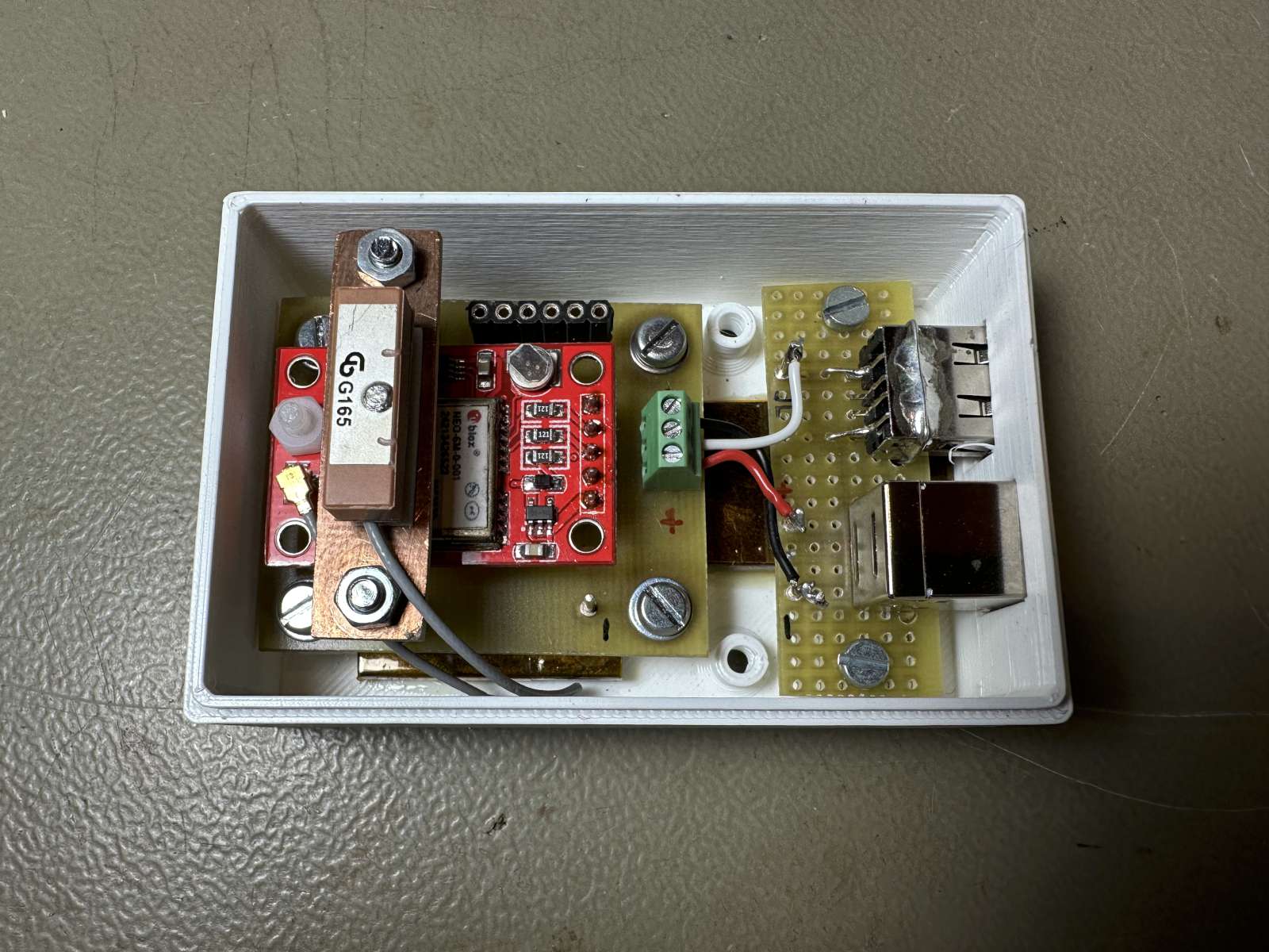
Inside view of the GPS receiver module. (click to enlarge)
When you power up the receiver, it needs a few minutes until a fix is found. As soon as it locks on a good GPS signal the pulses on the pulse per second (PPS) pin start and continue every second for as long as the signal is present. I only tried with a NEO-6, but I think that all NEO-6, 7 and 8 GPS modules will work too, as long as they provide a 100ms PPS signal.
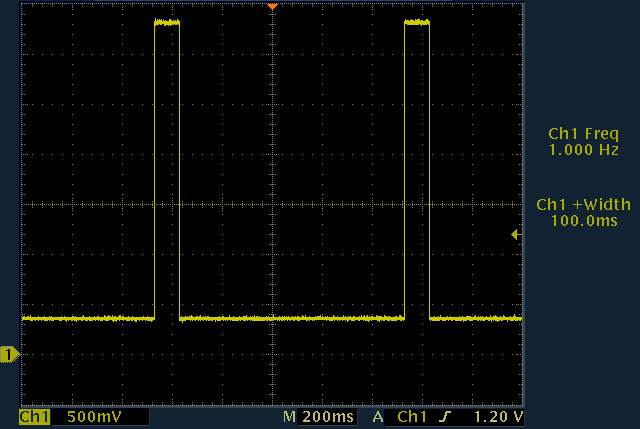
The pulse per second (PPS) signal provided by the GPS receiver.
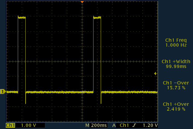
Voltage on the electromagnet coil.
The clamping effect of the flywheel diode is visible as an undershoot then
the voltage drops.
Of course the GPS receiver also needs an antenna that in my case it was supplied with the module. I mounted it on a piece of circuit board held over the module itself by two M3 screws. This is a convenient location as the short antenna cable can comfortably reach the connector on the GPS module. The antenna must be horizontal and must not be covered by metal parts.
The first prototype was supposed to be mounted outside and was in a weatherproof box. But I later discovered that I have enough GPS signal for good indoor reception if I'm close to the window, so I changed the box to a 3D-printed one that I placed on the window sill. Here too, I added a piece of iron to the bottom of the box to make it heavier and prevent it from being pulled by the cables. It weighs about 80g but it's not critical: it just needs to be heavy enough.
For letting a wire inside the grandfather's clock I had to drill a hole. This is the only invasive modification of the clock, as all the rest can be cleanly removed. I decide to drill in the clock base which is its least visible side. As long as you don't open the front door and stick your nose inside, you won't notice that there is a hole.
The bob swinging over the electromagnet. (click to enlarge)
For powering the whole system with 5VDC used an USB wall wart so that I don't have to design a power supply, deal with dangerous voltages such as 230VAC and all the EMC filtering is already done. Furthermore, USB cables are easy to find in a convenient length, they have small connectors and are available in white. I wanted to have white wiring so that it's not too visible on the wall between the clock and the window. I also decided to use an USB cable to carry the pulses to the electromagnet... it's not really compliant to the standard but I wanted the cable to be white and it doesn't do anything bad, it's a 5V signal anyway... a round DC connector would have been a better choice, but I only had black ones.
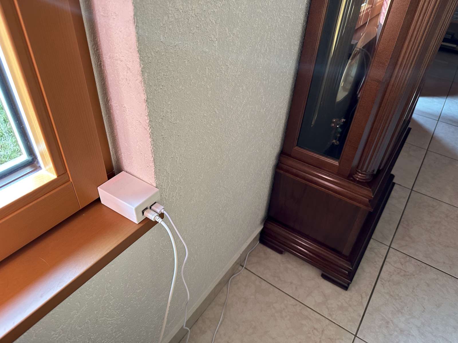
The GPS receiver on the window sill next to the grandfather's clock. (click to enlarge)
First I stopped the clock and let the pendulum rest at its bottom dead center. I pre-adjusted the height of the electromagnet to be about 5mm below the steel disk. I then carefully moved the base left/right and forward/backward until the electromagnet was centered below the steel disc. I now used the adjustment screw to raise the electromagnet until it touched the steel disk. To prevent scratching I placed a sheet of paper in-between. I now lowered the electromagnet by exactly two turns (1.0mm) and started the pendulum. I let it run for a few hours and remarked that at this distance the clock didn't synchronize. So I turned the screw by, say, 15° to make the electromagnet closer and let it run for a few hours. I continued like this until synchronization was achieved. Then I tightened the two screws in the slot to makes sure it won't move. Done.
With the pendulum stopped at its bottom dead center the electromagnet
is placed exactly below, here seen from the front and from the side.
(click to enlarge)
It's easy to tell if the pendulum is synchronized or not by just watching the LED. When it's synchronized it always flashes every time the bob passes over the electromagnet. When it's not synchronized, it sometimes flashes in different places and sometimes over the electromagnet. One observation is not enough and one has to observe it several times a few hours apart: if it always flashes over the electromagnet it's synchronized.
Watch a movie showing the pendulum swinging over the electromagnet:
pendulum-swinging.mp4
(2,168,292 bytes, 13 s, H264,
848 × 480, 30 fps).
If the electromagnet is too far away the clock will not synchronize. If it's too close, the amplitude decreases so much that the clock cannot tick anymore. In this case, the pendulum still swings moved by the energy of the electromagnet but the amplitude of the oscillations is too small for the escapement to work. Between these two conditions there is a sweet spot where it works just right. And this sweet spot is maybe 0.1mm wide. So the adjustment is fiddly, but once you have it right it works fine.
The system is now running since about two months and I'm happy with it. The clock is perfectly on time. The chimes, however, don't start exactly at "zero-zero" seconds at the top of the hour: it's a mechanical clock... it has a seconds hand but it's just for "esthetics". The chimes are driven by the minute wheel and the minute hand is not perfectly aligned with the chime mechanism. Aligning it is another deep rabbit hole that I may fall down in the future, but for the moment I decided it was good enough.
The nice thing of this system is that if the power or the GPS signal is lost, the clock keeps ticking on its own pendulum. But as soon as the pulses are back it synchronizes again. It may however gain or lose a few seconds when this happens, as without the pulses the pendulum is free to drift. But that's ok: power outages are very rare, don't last long and a few seconds are not visible on the minute hand.
Of course, this will only make sure that the pace of the clock is correct; it will not set the time on the dial like modern radio-controlled clocks do. I still had to set the time once when I started the clock and I'll have to readjust it twice a year to follow daylight savings time. But that's ok. And I still have to wind up the weights once a week, but as long as it keeps ticking it won't need any further adjustment: it will always display the correct time.
In conclusion, it turned out that synchronizing the clock was quite easy to do and worked on the first try. The electrical part is really easy thanks to these cheap and ready to go GPS modules that basically already provide the perfect signal straight out of the box. The mechanical part however turned out to be more involved but mostly because I wanted it to look as nice as a clock mechanism.
| [1] | Johannes Graf. Les temps modernes, la mesure du temps entre passé et présent. Deutsches Uhrenmuseums Furtwangen, 2006. |
| [2] | Paul A. Tipler. Invito alla fisica. Zanichelli, Bologna (Italy), 1995, Volume 2, Section 15.4, p350. |
| [3] | Christiaan Huygens. Letter number 1338 from Christiaan Huygens to R. Moray. Feb. 27, 1665. |
| [4] | M. Jufer. Traité d'Électricité, Vol. IX: Électromécanique. Presses Polytechniques et Universitaires Romandes, 1995, section 7.3.4. |
| [5] | Vacheron Constantin, Public domain, via Wikimedia Commons. commons.wikimedia.org, file 1843. |
| [6] | C.-A. Reymondin, G. Monnier, D. Jeanneret, U. Pelaratti. Théorie d'horlogerie. Fédération des écoles techniques (Le Locle - Suisse), 1998, section 7.2.2, page 131. |
| [7] | Museum of the Castle of Burgdorf (Schloss Burgdorf), Burgdorf (Switzerland) |
| [8] | Website of the company Mobatime AG, www.mobatime.ch |
| Home | Electronics | Page hits: 014237 | Created: 07.2023 | Last update: 08.2023 |