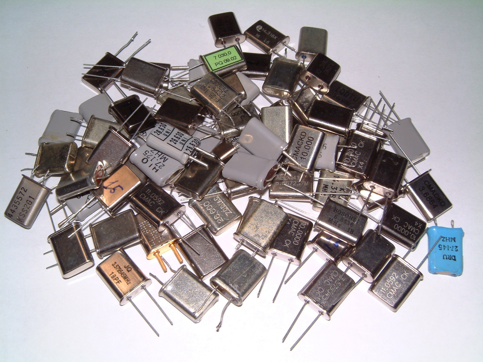
Some HC49 quartz crystals. (click to enlarge)
For building a good CW/SSB receiver a crystal ladder filter is often a very good option. One needs a band-pass filter with very sharp transitions between pass-band and stop-band in order to select only the desired signal and disregard the rest. Ceramic filter usually have wider pass-bands and are only intended for AM or FM reception; for SSW and CW they are too wide and don't offer enough selectivity. A mechanical filter is indeed a better option but is also very expensive, way too much for a simple home-brewed receiver. Very good crystal filters can also be readily bought, but they are hard to find and their price is also very high. A crystal ladder filter is a very good compromise: it offers good characteristics for a reasonably low price. It's drawback is that it requires quite some work to get it working and cannot be mass produced, as may crystals must be carefully measured and only a few will be finally used in the filter. Another drawback is that the exact IF (intermediate frequency) is determined by the very crystals you measured and is usually not a nice number. But these are still very reasonable compromises for a home-built project.
Another application for a crystal ladder filter is for building an SSB modulator or transmitter. Again there are several options: ceramic filters can also do the job and are cheap, but their performance is not as good; mechanical filters or readily built crystal filters are excellent but very expensive. One could choose a different method of modulation and use 90° phase shifters, which work well but requires a lot of components. Here, again, a crystal ladder filter is a very good option.
For CW a bandwidth of 500 to 800 Hz is adequate and for SSB the bandwidth should be in the 2500 to 3000 Hz range.
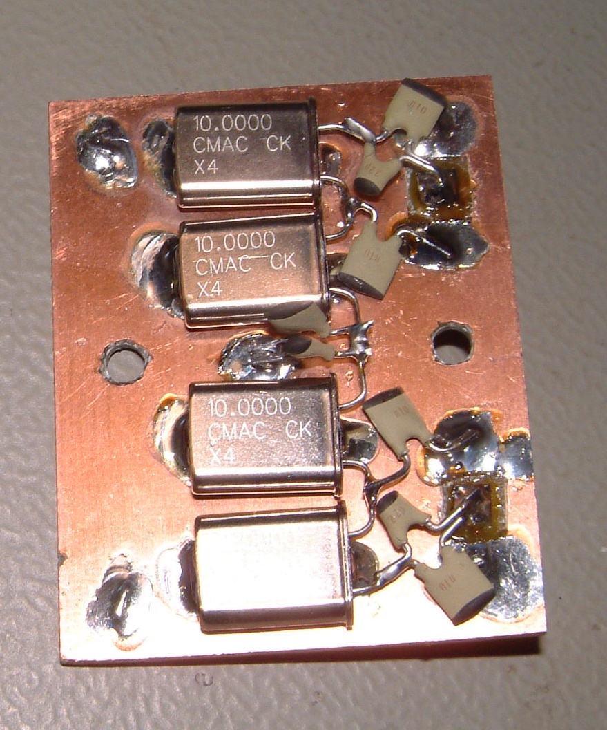
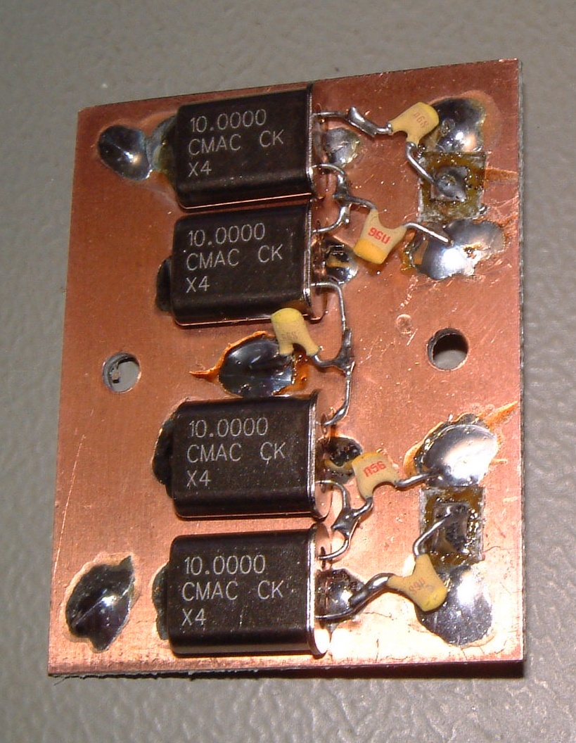
The ladder filter uses several identical crystals (in these pages only filters with 2, 3, 4, 6 or 8 crystals are discussed) and a few capacitors in order achieve the desired bandwidth. Since all crystals must be identical, choosing them all from the same manufacturer and from the same production batch is already a good idea, but this won't probably be enough and the best solution is to buy a lot of many crystals (40 or so), measure them all and select a few with very similar characteristics. Using non selected crystal will significantly degrade the performance of the filter.
Some HC49 quartz crystals. (click to enlarge)
The main advantage of the ladder filter is that all the crystals are identical and there is no need for having crystals cut at specific (and non-standard) frequencies. Any AT-cut crystal will do no matter if it was designed for serial or parallel resonance. Cheap CPU crystals such as 3.2768 MHz or 4 MHz work perfectly; TV crystals cut at 4.433619 MHz or 3.579545 MHz also work very well. Overtone crystals will also work, but at their fundamental frequency; for example CB crystals originally cut for 27 MHz (3rd overtone) can be used for a filter at about 9 MHz.
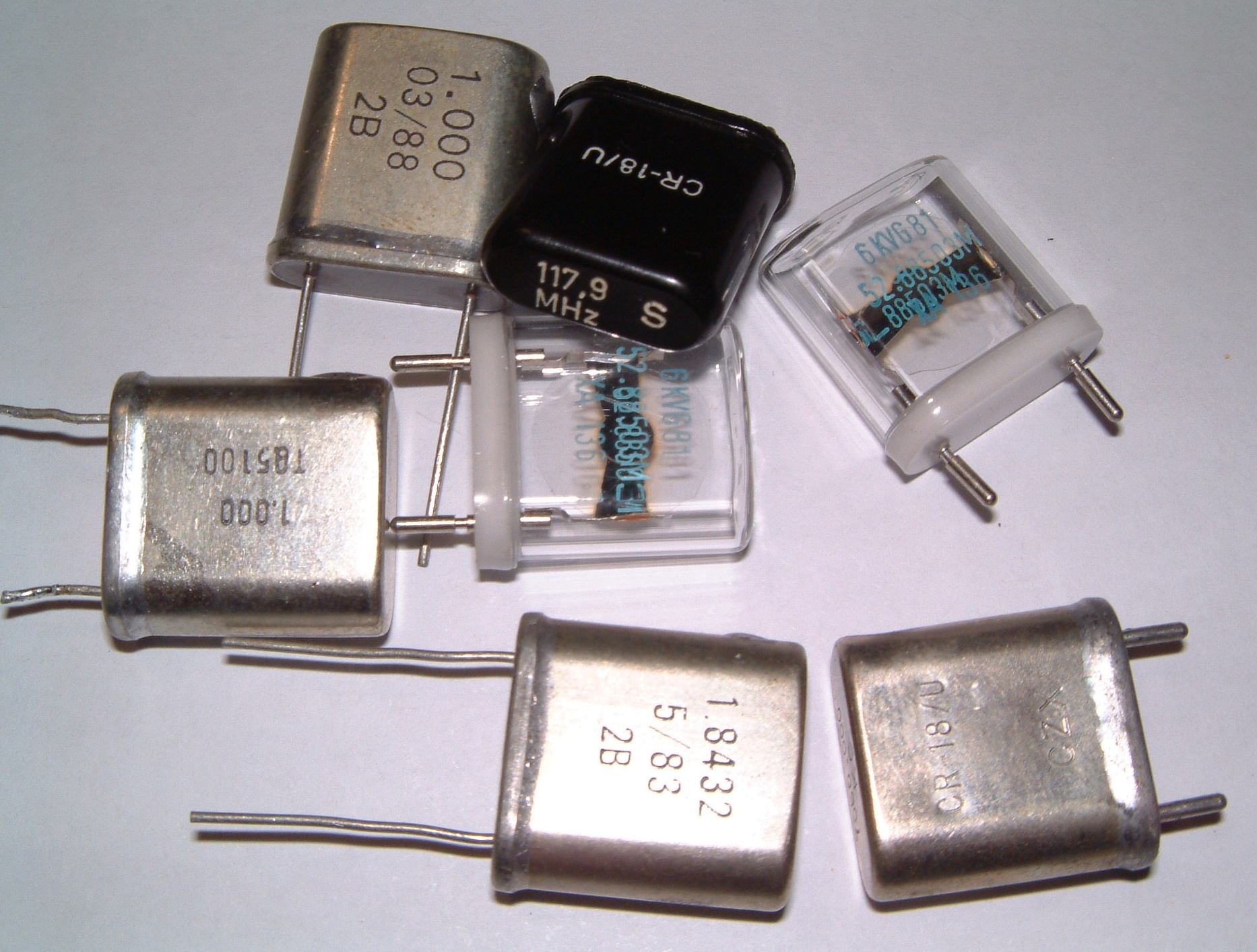
Some HC18 quartz crystals. (click to enlarge)
The two calculators in this page help in selecting the crystals, determining their equivalent parameters and calculating the filter. The center frequency of the filter will be roughly the one written on the crystal, but not exactly. It will be several kHz apart and its exact value depends on the type of crystal, its resonance type and its cut. But the calculator in this page will determine it exactly.
The bandwidth is in the hundreds of Hz to the thousands of Hz, again depending on the crystals. The characteristic impedance of the filter depends on the bandwidth: narrow bandwidth filters have very low impedance (down to a few Ohms) and wider filters have higher impedance (a few hundreds Ohms) but the maximum bandwidth is limited by the type of crystals and the filter configuration.
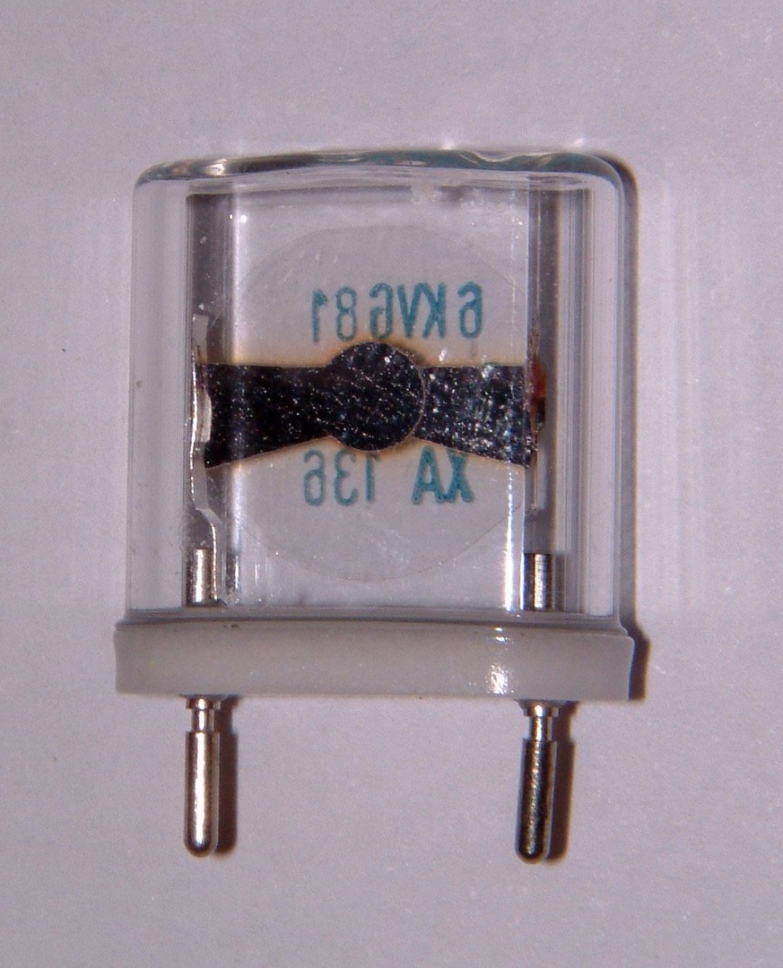
A crystal with transparent case. (click to enlarge)
For those who want to know what's inside a quartz, this is a picture of a crystal with transparent case: the crystal itself is the disc in the middle, which is also transparent... after all quartz is transparent. The leads are connected to two metallized strips on the quartz disc, one on each side.
So, the design of a ladder filter is done in the following steps:
In order to design a crystal ladder filter, knowing the exact crystal characteristics is mandatory. Unfortunately the information printed on the component itself (or available on the data-sheet) is usually not enough.
Each crystal can be imagined as an RLC resonant circuit with one series capacitance Cs and one parallel capacitance Cp (see figure below). For our ladder filter, we need the exact value of Cs.
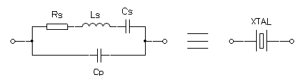
Electrical model of a crystal.
Even if the manufacturer doesn't specify this value we can stll measure it yourself with the help of a little test circuit. It will allow measuring Cs, Ls and Cp. Unfortunately Rs cannot be measured with this method, but its value is usually in the tens of Ohms.
First you need to build the test circuit. A solid construction with a good ground plane will give more accurate results. Crystal sockets should be avoided as introduce stray capacitance. For the same reason and in spite of what indicated in the schematic, the use of a switch is not recommended and one should solder directly the 10 pF and 27 pF capacitors to the quartz. I also recommended to measure these two capacitors precisely and use the measured values as C1 and C2 to calculate the equivalent parameters. C1 and C2 should also be NP0 ceramic capacitors to avoid errors due to temperature variations.
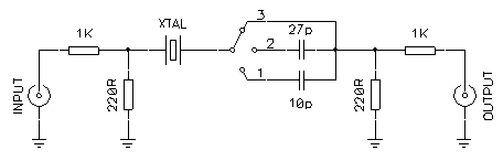
Crystal parameters measurement circuit.
This test setup is a very simple crystal filter. With it we determine on which frequency the attenuation is minimum (series resonance of the crystal) and maximum (parallel resonance) with the quartz alone and with 2 different series capacitors.
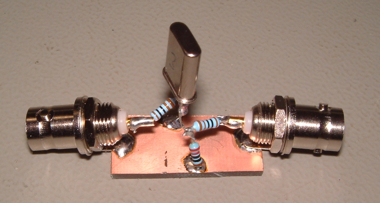
Picture of the test setup (click to enlarge).
There are three ways of doing this: one can connect a tunable RF generator to the input and an oscilloscope on the output (or an RF voltmeter), one can connect a noise generator on the input and an HF receiver on the output, or one can use a spectrum or network analyzer. Using instruments with a resolution of at least 10 Hz is strongly recommended.
First connect the 10 pF capacitor (position 1) and look for the frequency that gives the maximum signal at the output (minimum attenuation). This will be fs1. Than connect the 27 pF (position 2) and look for the maximum output again, and this will be fs2. Now connect the crystal directly (position 3) and look for maximum output (frequency fs3) and also for the minimum one (frequency fp).
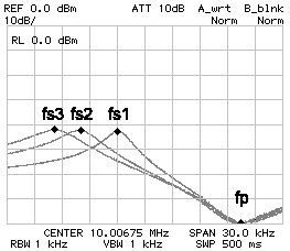
Crystal frequency response.
The frequency response of this filter looks something like the figure above. You will always get fs3 < fs2 < fs1 < fp. Now, just enter those values in the form below and hit the "calculate" button. For designing the filter you will need fs3, fp and Cs.
The "Transfer results" button copies the parameters of the crystal we just found in the filter calculator below.
Now that we know the crystal parallel and series resonance and its series capacitance we can design our bandpass filter with the following calculator. It can calculate Butterworth and Tschebyscheff filters from 2 to 8 poles and, depending on the desired number of poles, the filter will be composed by 2 to 8 identical crystals and some capacitors.
The number of poles of the filter equals the number of crystals and depends on how many identical crystals one happens to have. More poles equals a better filter, i.e. with steeper response and better ultimate attenuation.
If no bandpass ripple is allowed the filter will be a Butterworth one, the transitions between pass-band and stop-band will not be very steep and the ultimate attenuation (horizontal asymptote) will be poor. If some bandpass ripple is allowed the filter will be Chebytheff one with much stop-band and ultimate attenuation characteristics. The higher bandpass ripple is allowed the better the filter will perfoorm in its stopband, it's a matter of choosing the best compromise.
Quartzes are used in their fundamental mode (even if they are overtone) and in their series resonance (even if they were designed for parallel mode operation).
It's also important to select crystals with very similar characteristics; the resonance frequencies should be within a maximum of 100 Hz, the closer the better.
The target bandwidth is the bandwidth the filter should pass: the maximum possible bandwidth depends on all the data entered and is usually only a few kHz.
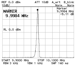
Now let's have a look at two examples. I found two dozens of 10 MHz crystals, all from the same brand and all from the same batch. The series resonance frequency of all of them was measured and 4 crystals with series resonance frequencies within 95 Hz were found. 4 other crystals had their series resonance within 136 Hz, all the rest was spread between 9.991'974 MHz and 9.993'963 MHz. This allowed building two 4-pole filters around 10 MHz, one for CW and one for SSB. When selecting crystals, it's the series resonance that matters; at least for filters with all the crystals in series as the ones described in these pages.
It's also a good idea to put the crystals in a symmetrical way in the filter. For example, if you have four crystals, you could put the two lowest frequencies in the middle and the two highest on the edges; or vice-versa.
Using the test setup the following parameters were measured:
| fp = | 10.017'730 | MHz |
| fs1 = | 10.003'870 | MHz |
| fs2 = | 9.999'730 | MHz |
| fs3 = | 9.996'490 | MHz |
| C1 = | 10.29 | pF |
| C2 = | 33.77 | pF |
The related script found the characteristics parameters as follows:
| Cs = | 27.132 | fF |
| Ls = | 9.343 | mH |
| Cp = | 6.385 | pF |
By setting a bandpass ripple of 0.5 dB (Tchebycheff) for 4 crystals (poles) and a target bandwidth of 2.7 kHz, the simulation found the following values:
| Center frequency: | f0 = | 9.998'143 | MHz |
| Ultimate attenuation: | Uatt = | 104.9 | dB |
| Filter impedance: | Z0 = | 102.7 | Ω |
| Capacitor values: | CP1 = | 131.0 | pF |
| CP2 = | 155.9 | pF | |
| CS1 = | 155.9 | pF |
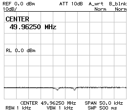
By rounding the capacitor values to the standard 150 pF and 120 pF the response of the filter was as follows (by directly connecting the filter to 50 Ω, without impedance matching):
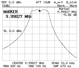
Frequency response CS1 = CP2 = 150 pF
CP1 = 120 pF Z = 50 Ω.
This response is not bad, but the bandwidth is not as wide as supposed (2360 Hz instead of 2'700 Hz) and the ripple is a bit too high (about 2 dB), but by adjusting the capacitor values to 120 pF and 100 pF, and by finding the correct impedance of 207 Ω (see below) the following response was achieved:
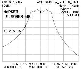
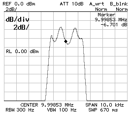
Frequency response of the 2.7 kHz filter;
CS1 = CP2 = 120 pF
CP1 = 100 pF
Z = 207 Ω ;
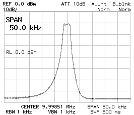
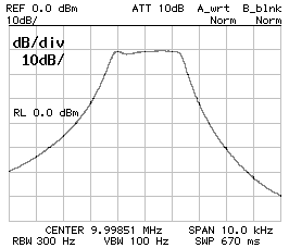
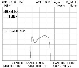
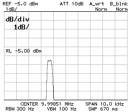
50 kHz span (left), 10 kHz span (middle) and 1 dB/DIV
(right).
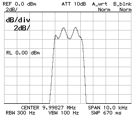
These are the characteristics of the final filter:
| Capacitor values: | CP1 = | 100 | pF |
| CP2 = | 120 | pF | |
| CS1 = | 120 | pF | |
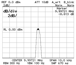
| Bandwidth (-3 dB): | B-3dB = | 2'640 | Hz |
| Bandwidth (-60 dB): | B-3dB = | 13'880 | Hz |
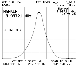
| Center frequency: | f0 = | 9.998'510 | MHz |
The ripple in the pass-band is now 1 dB, which is still greater than what was specified, but with those crystals it wasn't possible to do any better.
2.7kHz crystal ladder filter. (click to enlarge)
By setting a bandpass ripple of 0.5 dB (Tchebycheff) for 4 crystals (poles) and a target bandwidth of 0.6 kHz, the simulation found the following values:
| Center frequency: | f0 = | 9.996'850 | MHz |
| Ultimate attenuation: | Uatt = | 159.4 | dB |
| Filter impedance: | Z0 = | 20.0 | Ω |
| Capacitor values: | CP1 = | 673.0 | pF |
| CP2 = | 801.1 | pF | |
| CS1 = | 801.1 | pF |
Since the SSB filter required smaller capacitor than calculated, it was decided to use 680 pF and 560 pF. The impedance was found to be 34 Ω and the filter performs as follows:

Frequency response of the 600 Hz filter;
CS1 = CP2 = 150 pF
CP1 = 120 pF
Z = 50 Ω ;
10 dB/DIV (left) and 1 dB/DIV (right).
These are the characteristics of the final filter:
| Capacitor values: | CP1 = | 560 | pF |
| CP2 = | 680 | pF | |
| CS1 = | 680 | pF | |
| Bandwidth (-3 dB): | B-3dB = | 520 | Hz |
| Bandwidth (-60 dB): | B-3dB = | 4'360 | Hz |
| Center frequency: | f0 = | 9.997'230 | MHz |
There is no pass-band ripple and the filter is still narrower than expected, but for CW a 520 Hz filter is even better than 600 Hz.
600Hz crystal ladder filter. (click to enlarge)
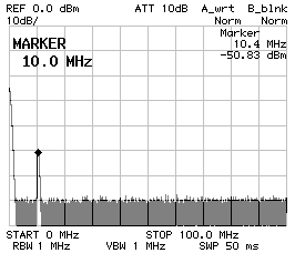
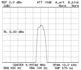
It's often told that crystals have several resonances: there is the fundamental, several overtones and some stray resonances. The question is if the filter has other stray pass-bands. The two charts below show a four poles Tchebycheff filter filter with 220 pF and 330 pF capacitors. It's clear that there are no stray pass-bands in the nearby of the desired pass-band (the figure of the shows a span of 200 kHz). It's not easy to measure the response for a wider span, because the filter is very sharp and the spectrum analyzer may not see it if this falls between two measurement points; at least with the one I have. As one can see on the figure on the right (which covers from 0 Hz to 100 MHz), there are no visible undesired pass-bands, but the main pass-band appears very small and this is because of the limited amount of measurement points of the analyzer. The peak at 0 Hz is normal for almost any spectrum analyzer and has nothing to do with the ladder filter.
Frequency response
CS1 = CP2 = 220 pF
CP1 = 180 pF
Z = 50 Ω
200 kHz span (left) and 100 MHz span (right).
Considering that the crystals have a fundamental resonance around 10 MHz, they should also have overtone resonances roughly at every odd multiple of 10 MHz. The two charts below show the response of a four poles Tchebycheff filter with 680 pF and 560 pF capacitors around 30 MHz (left) and around 50 MHz (right). A resonance is indeed there but the peak is small enough to be neglected (at least with this particular model of crystals).

Frequency response
CS1 = CP2 = 680 pF
CP1 = 560 pF
Z = 34 Ω
30 MHz center frequency (left) and 50 MHz center frequency (right).
Even if it's not possible to state for sure that there are no stray pass-bands this is usually not a problem, since there are none nearby the true pass-band and if this would be the case, a simple LC filter would suffice to remove any stray response.
As it was explained in the previous example, there is always some differences between the calculated filter response and the results of the real measurements. The main reasons are errors in determining the crystal equivalent parameters, wrong capacitance values and crystal mismatch.
Measuring the series and parallel resonance of a crystal it's not easy and it's hard to tell the exact frequency of a maximum or a minimum within a few Hz. Unfortunately, when calculating Cs, a little change in the frequencies yields in a large change in the result.
The simulator finds theoretical capacitance values that in practice must be rounded to the closest available values. Furthermore, the exact capacitance of a real capacitor varies from one capacitor to another and is also function of the temperature. Finally, stray capacitance plays a role; especially when capacitor values are small. The result is that the capacitors "look bigger" by a few pF. Using capacitive trimmers could be a solution, but I'm not sure it's worth the effort.
Finally, even if all the crystals look identical, they come out of the same stock and have been selected to have close resonance frequenciesy, they are not really identical always producing higher ripple in the pass-band than planned.
Trying to manually guess capacitor values from scratch is a nightmare since there are too many adjustments to make, but it's quite ok to tune a filter a little bit in order to make the pass-band just a smidge wider or narrower. The idea is to keep the same ratio between all the capacitors and just multiply them all by a common factor. Increasing the capacitance will make the bandwidth narrower and decreasing it will make the bandwidth wider. The bandwidth will not change symmetrically: the right side changes much more than the left one. Keep in mind that scaling capacitor values will also change the characteristic impedance of the filter and a different matching will be required (see below). Changing the ratio between the capacitors is generally not a good idea: this will completely change the filter response and usually yields to significant ripple in the pass-band.
The following table summarizes the changes in the filter response by scaling all the capacitors by (about) the same factor. For simplicity, all the filters are directly connected to 50 Ω and this explains the high pass-band ripple in wide filters. All filters are 4-poles Tchebycheff filters.
CS1 = CP2 = 120 pF ;
CP1 = 100 pF ;
BW–3dB = 2'760 Hz ;
BW–60dB = 11'520 Hz ;
f0 = 9.998'530 MHz ;
10 dB/DIV (left) and 2 dB/DIV (right).
CS1 = CP2 = 150 pF ;
CP1 = 120 pF ;
BW–3dB = 2'360 Hz ;
BW–60dB = 9'920 Hz ;
f0 = 9.998'270 MHz ;
10 dB/DIV (left) and 2 dB/DIV (right).
CS1 = CP2 = 220 pF ;
CP1 = 180 pF ;
BW–3dB = 1'580 Hz ;
BW–60dB = 8'260 Hz ;
f0 = 9.997'760 MHz ;
10 dB/DIV (left) and 2 dB/DIV (right).

CS1 = CP2 = 390 pF ;
CP1 = 330 pF ;
BW–3dB = 960 Hz ;
BW–60dB = 5'540 Hz ;
f0 = 9.997'480 MHz ;
10 dB/DIV (left) and 2 dB/DIV (right).


CS1 = CP2 = 470 pF ;
CP1 = 390 pF ;
BW–3dB = 760 Hz ;
BW–60dB = 4'940 Hz ;
f0 = 9.997'340 MHz ;
10 dB/DIV (left) and 2 dB/DIV (right).

CS1 = CP2 = 560 pF ;
CP1 = 470 pF ;
BW–3dB = 660 Hz ;
BW–60dB = 4'440 Hz ;
f0 = 9.997'270 MHz ;
10 dB/DIV (left) and 2 dB/DIV (right).
CS1 = CP2 = 680 pF ;
CP1 = 560 pF ;
BW–3dB = 540 Hz ;
BW–60dB = 4'060 Hz ;
f0 = 9.997'210 MHz ;
10 dB/DIV (left) and 2 dB/DIV (right).
The type of crystal and the value of the capacitors determine the characteristic impedance of the filter. If the filter is not matched on its impedance, the frequency response will vary. Fortunately a reasonable impedance mismatch has little influence on the bandwidth but has a significant influence on the pass-band ripple. In order to determine the impedance of the filter a spectrum or network analyzer is required. The easiest way is to add in series or in parallel with each end of the filter a trimmer in order to rise or drop the impedance (on one side the trimmer will be in series and on the other one in parallel). This matching method is of course lossy, but is very easily adjustable. Just adjust the two trimmers for the flattest response possible, then measure their with a multimeter and calculate the impedance. Of course, when the impedance of the filter is known, a true and low-loss matching network must be designed, usually based on an LC circuit; this, unfortunately is not covered in this article, but I suggest using a Smith-chart software to solve this problem.
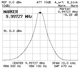
Filter connected to 50 Ω (mismatched) ;
BW–3dB = 2'760 Hz ;
BW–60dB = 11'520 Hz ;
f0 = 9.998'530 MHz ;
10 dB/DIV (left) and 2 dB/DIV (right).
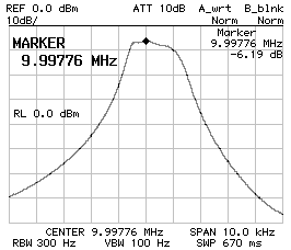
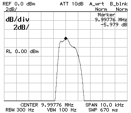
Filter matched to 207 Ω ;
BW–3dB = 2'640 Hz ;
BW–60dB = 13'880 Hz ;
f0 = 9.998'510 MHz ;
10 dB/DIV (left) and 1 dB/DIV (right).
The responses above refer to a filter with CS1 = CP2 = 120 pF and CP1 = 100 pF. The extra losses due to the resistive matching is clearly visible since the flatter response is a few dB lower. All filters are 4-poles Tchebycheff filters.
Back in the early 2000s I was designing a CW/SSB shortwaves transceiver and I needed two narrowband filters. So I started looking in my old magazines for articles on how to design crystal ladder filters; I know I had something somewhere. And sure enough [1] and [2] described a way of how to do it, but the math was too complex for a pocket calculator and the suggested BASIC code was already obsolete, even back then. But for such complex formulas some sort of computer program was needed anyway, so I decided to implement the algorithms in JavaScript, directly allowing this simple web crystal ladder filter calculator. Later on, a visitor of this site suggested [3] that, in my opinion, is even a better source on the topic. Since then, I used this calculator do design several other filters, always with good results. So, I hope that this may be helpful in your own designs.
| [1] | P. Magnin F6HYE, B Brocard F3BB. Calcul et réalisation de filtres à quartz en échelle. Ondes Courtes Informations N158, Spécial Noël 1985, pages 130-136. |
| [2] | J. Durand FC1QY. Conception et réalisation des filtres à quartz en échelle. Ondes Courtes Informations N183, Mai/Juin 1992, pages 10-14. |
| [3] | J. A. Hardcastle G3JIR. Computer-aided ladder crystal filter design. Radio Communication, May 1983, pages 414-420. |
| Home | Electronics | Page hits: 129283 | Created: 05.2005 | Last update: 11.2022 |