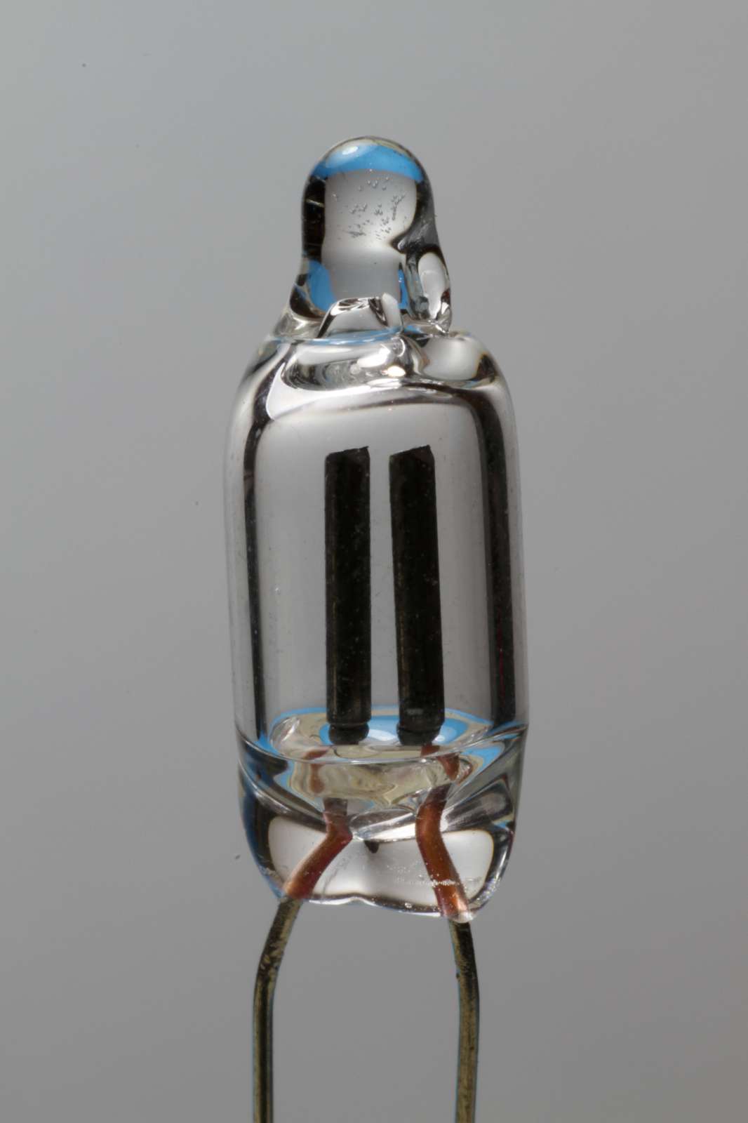
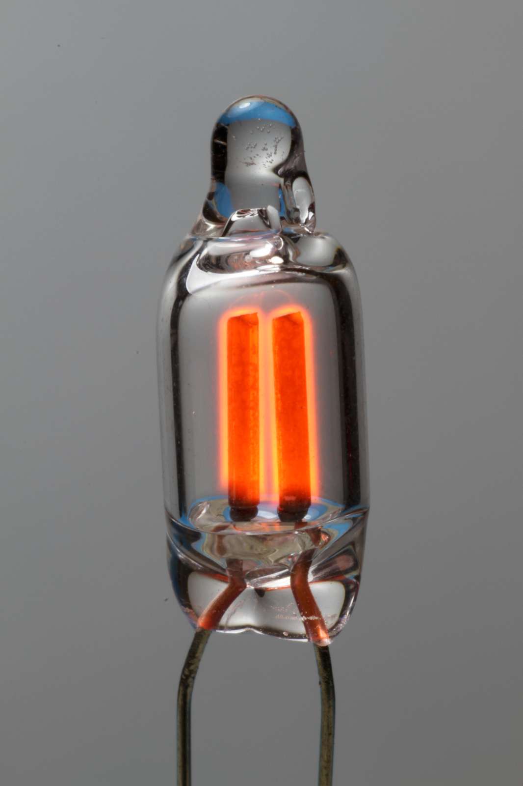
Close-up of a common NE-2 like neon glow lamp, "off" on the left and "on" on the right. (click to enlarge).
I always got a fascination with neon glow lamps. I don't know why, maybe simply because they glow in the dark. Maybe because they don't always burn with a steady light but sometimes shake a little bit, like if they were alive or if they were burning like a flame. Maybe because the light seems to come out of nothing, out of empty space, like a glass bulb full of light... I know, I know, it's the gas that glows, but you don't really see the gas; when the lamp is off, the gas is completely transparent.
Close-up of a common NE-2 like neon glow lamp, "off" on the
left and "on" on the right. (click to enlarge).
Neon glow lamps are obsolete today. LEDs have better efficiency, longer lifetime and are cheaper. Still, glow lamps are very interesting devices. Not only they produce light, but have also interesting electrical (and physical) properties and may have other uses than simply producing light. The goal of this page is to present some of these properties and applications, from the very basic to the strangest ones.
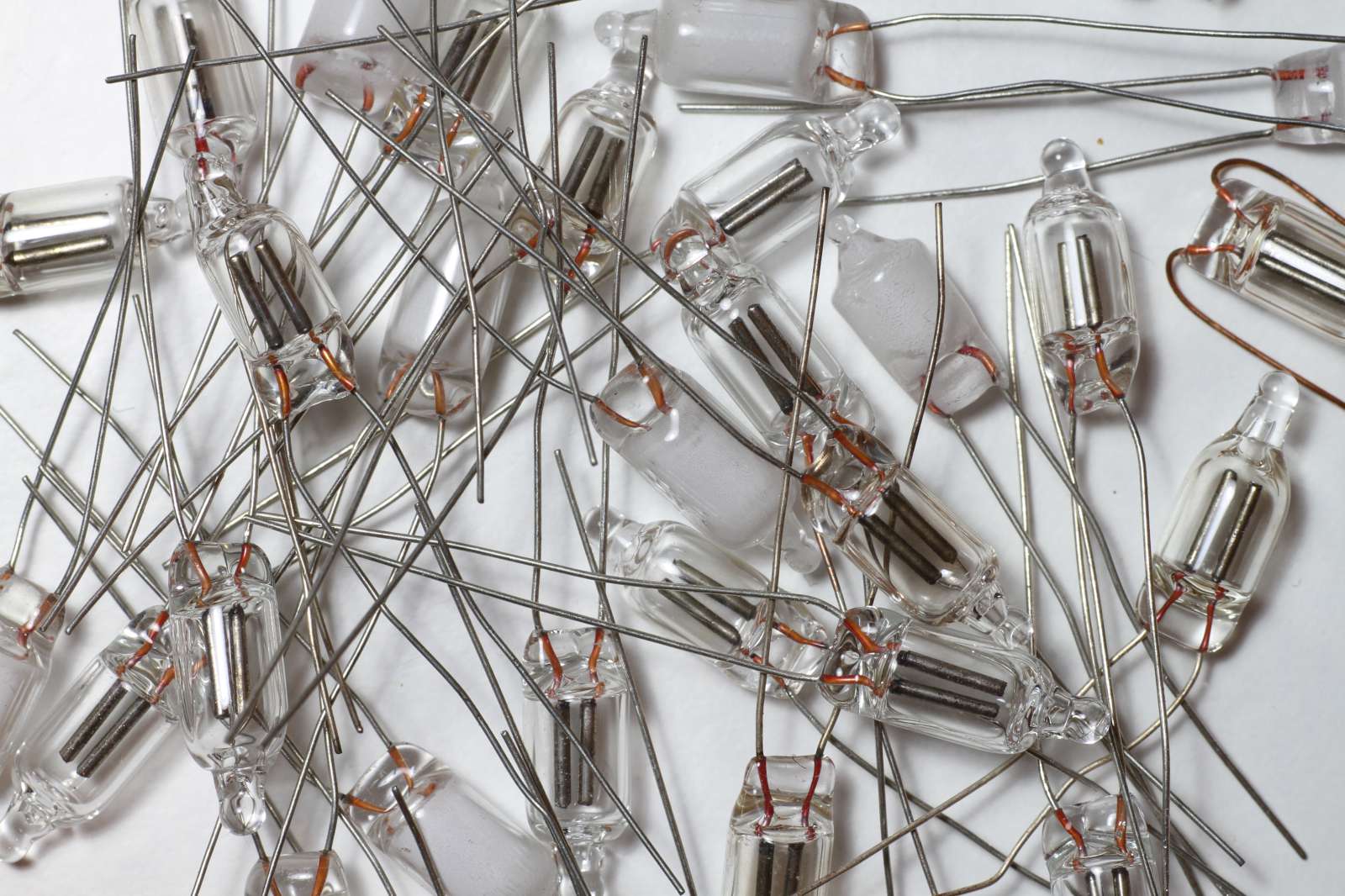
Picture of a few dozen glow lamps. (click to enlarge).
Remark: the majority of the circuits presented here is directly connected to the mains and presents the risk of electrical shock. They are intended for experienced technicians. Only attempt building these circuits or experimenting with them only if you know what you’re doing, at your own risk. Do not forget to read my disclaimer.
Neon glow lamps are a sort of miniature gas discharge lamps. The lamp is composed by a sealed glass bulb containing two electrodes and a low pressure noble gas mixture. When current flows through the lamp, the gas immediately surrounding the negative electrode glows. This glow is usually orange in color and not very bright.
It's a very old technology: the glow lamp we know today in the form of a small glass bulb was patented in 1919 (US patent 1316967), but gas discharge tubes were known long before. Geissler tubes, for examples, were invented in 1857.
These lamps glow with a very low current and a relatively high voltage, normally in the 0.1 to 10 mA range and 50 to 100 V, depending on the desired brightness and the type of bulb. This makes them ideal for running on mains voltage with just an additional resistor. For this reason, their most common use is as mains voltage indicator lamp.
To start the lamp, a higher slightly voltage is required, something like 10 to 20 V more than the burning voltage, so no special starting circuits are required as the mains voltage is normally high enough.
Neon glow lamps cannot be directly connected to a voltage source without a current limiting device (ballast). Fortunately, a simple resistor is usually all it takes to limit the current. Models that can be directly plugged to mains voltage (120 or 230 VAC) are readily available and are basically a neon glow lamp with a built-in ballast resistor.
The lamp is composed by a sealed glass bulb. A multitude of sizes and types exist, but the most common these days is about Ø 5 mm and 12 mm long. The air inside is evacuated and bulb is filled with mixture of low pressure gases, around 99 % of neon and 1 % of helium or argon is typical. This particular mixture is called a Penning mixture and minimizes the ionization voltage. The pressure is somewhere between 1 and 25 mbar, depending on the tube design. [2]
Inside are two metal electrodes, usually made of nickel or molybdenum. To lower the ionization voltage they can be coated with barium or strontium, but the coating will degrade over time and electrical characteristics will drift as well. [2]
When a current flows though the gas, a red-orange glow appears around the negative electrode. Only the negative electrode glows, the positive one stays dark. If the current is alternating, both electrodes will appear to glow, but actually only the negative one glows at any given time; it just happens too fast for the eyes to see the glow flicker from one electrode to the other. As shown in the following pictures by the orientation of the diode, only the negative electrode glows; when no diode is connected, both electrodes appear to be glowing.
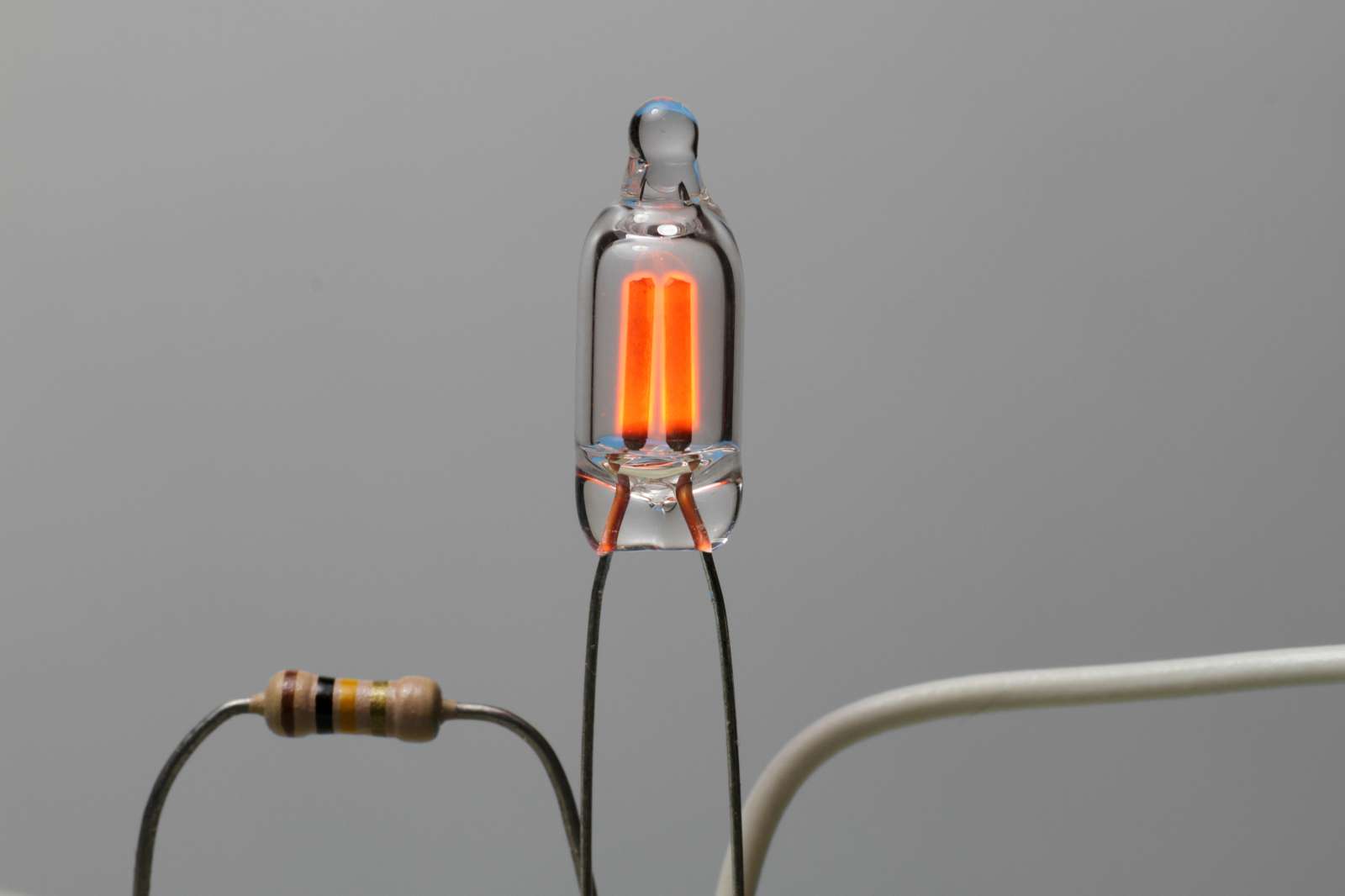
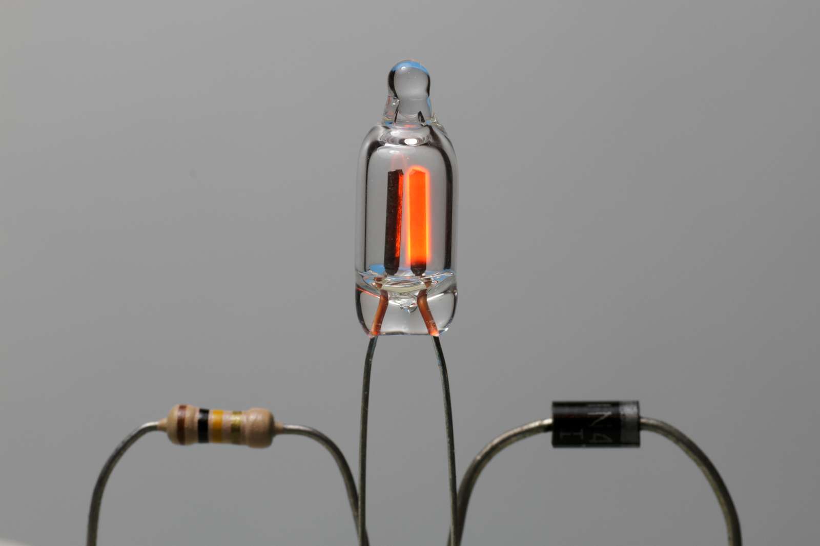
Pictures of the same neon glow lamp with the negative electrode on the
left (left), with AC (center) and with the negative electrode on the right
(right).
Please observe the orientation and presence of the diode.
(click to enlarge).
If needed, to prevent some parts of the electrodes from glowing, these regions can be coated with an insulating material. This is useful to concentrate the light on one side of the tube or to avoid glow on the connecting wires.
Pictures of two similar neon glow lamps.
The lamp on the left has bare electrodes and the glow is all around them.
The lamp on the right has the bottom part of the electrodes painted with an
insulating material: only the top part glows.
(click to enlarge).
The color of the light of a neon glow lamp is orange, but other colors (typically green or blue) can be obtained by using a different gas mixture and a fluorescent coating.
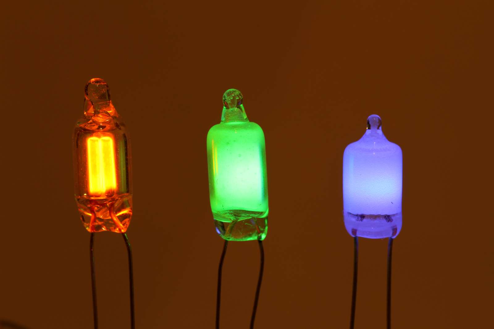
Picture of three glow lamps: orange, green and blue. (click to enlarge).
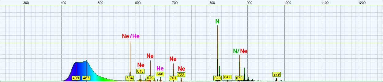
Let's have a look at the spectrum of a neon glow lamp. More precisely at the one on the left on the above picture. By looking at the spectral lines we can tell the composition of the gas inside the lamp. In this case we see that this lamp contains mainly neon, but also some helium and some argon. My cheap spectrometer is not very precise and the peaks are a few nanometer off from their true wavelength, still the different spectra are easy to recognize.
Because glow lamps work at room temperature, there are only a few elements that are gasses or liquid susceptible to vaporize in a low pressure atmosphere. These elements are hydrogen, helium, nitrogen, oxygen, neon, argon, krypton, xenon, mercury, and maybe chlorine and bromine. I based my analysis on the reference spectra I found on [5]
We clearly see that this "normal" neon glow lamp clearly contains neon because we recognize its typical emission peaks at 585, 614, 640, 703, 726 and 838 nm. It also contains helium that emits at 588 and 668 nm, but with my low precision spectrometer we cannot be sure if the peak measured at 584 nm is due to neon (585 nm) or helium (588 nm). We also see two peaks 752 and 810 nm emitted by argon. So we now know for sure that this lamp contains mainly neon (many strong peaks), but also some helium and some argon.

Spectrum of the light emitted by a neon glow lamp.
The wavelength in nm is on the horizontal axis and the amplitude in arbitrary
units is on the vertical one.
As one can see, the majority of the light is in the yellow to red part of the spectrum with very little green and no blue at all. This explains why neon glow lamps are commonly used in yellow, orange and red indicator lights but give vary bad results if used with a green or blue colored cover.
For green and blue lamps, nitrogen is used. It emits UV light at 214 nm and blue light at 422 nm. These photons can then be converted into the desired color by a fluorescent coating on the inside wall of the lamp. I don't know why, but the mercury and argon mixture typically used in fluorescent tubes is not suitable for miniature lamps.
By looking at the light spectrum of the green lamp (middle lamp in the above picture), we see many characteristic peaks of nitrogen: 747, 822, 868 and 871 nm. This last peak could also be due to neon that emits at 878 nm, but my spectrometer is not good enough to be sure. The bell-shaped peak at 525 nm is the light emitted by the fluorescent coating, while the UV radiation is blocked by the glass wall and cannot be measured. As a general rule, peaks emitted by a (low pressure) gas are thin and sharp, while peaks emitted by a solid are wider and bell-shaped.

Spectrum of the light emitted by a fluorescent green glow lamp.
The wavelength in nm is on the horizontal axis and the amplitude in arbitrary
units is on the vertical one.
In the spectrum of the blue lamp (on the right in the picture above), we also see many characteristic peaks of nitrogen at 822, 868 and 871 nm, but we also see neon at 585, 614, 640, 703, 726 and 878 nm, and helium at 588 and 668 nm. The bell-shaped peak at 439 and 437 nm is the light emitted by the fluorescent coating. Again, the UV radiation is blocked by the glass wall and cannot be measured.
Spectrum of the light emitted by a fluorescent blue glow lamp.
The wavelength in nm is on the horizontal axis and the amplitude in arbitrary
units is on the vertical one.
This spectrum looks suspect, use skepticism.
The electrical characteristics of fluorescent glow lamps are similar to normal neon bulbs but voltages are usually a bit higher. These lamps, when not powered, appear white instead of transparent.
Neon glow lamps use little power but are not very efficient: a NE-2H lamp is around 2.2 lm/W [2]; this is very far from the 100 or more lm/W that can deliver a modern fluorescent tube or LED (as of 2018).
Neon glow lamps have been produced in many sizes and shapes. The smallest I've ever seen are about Ø4 mm and 8 mm long with two thin leads to be soldered. The biggest are in the form of a pear-shaped light bulb roughly Ø 60 mm and E27 Edison screw base. But there are many variations and odd shapes.
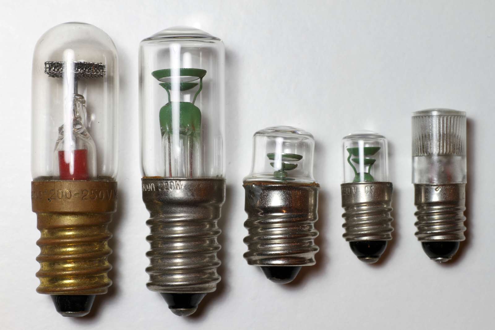
Five glow lamps with screw mount intended for mains indicator light
applications: the three on the left have an E14 socket and the two on the
right E10.
They all have an integrated ballast resistor and are all suitable for direct
connection to a 230 VAC mains. (click to enlarge).
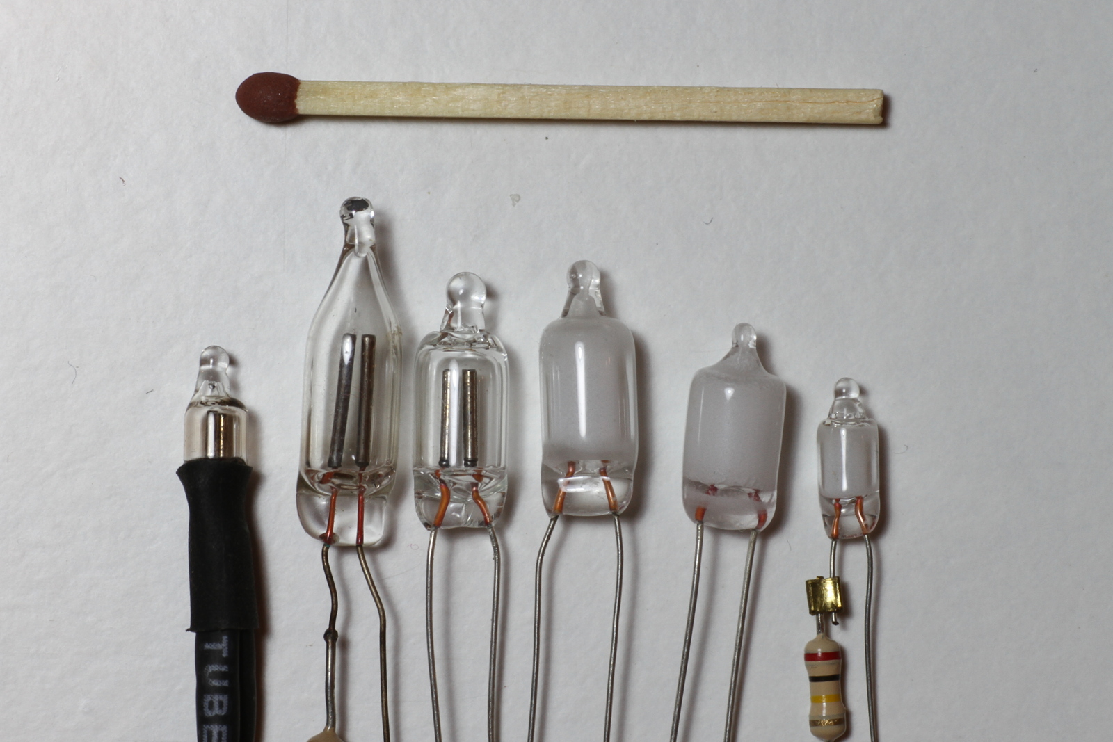
Six full glass glow lamps.
From left to right: a miniature neon glow lamp Ø 4 mm
× 8 mm, a true General Electric NE-2 neon glow lamp
Ø 6.35 mm × 27 mm, a common neon glow lamp
Ø 6 mm × 19 mm, a green fluorescent glow lamp, a
blue fluorescent glow lamp and a miniature green fluorescent glow lamp.
(click to enlarge).
A fuse-shaped glow lamp with asymmetrical electrodes.
This model doesn't have an integrated ballast resistor. (click to enlarge).
The electrical characteristics of neon glow lamps vary over time. Striking and maintaining voltages vary a lot in the first few hours of service: if these parameters are important for the application, the lamps should be aged before use. To do so, letting the lamp glow at its maximum current (or a bit more) for one or two days is often enough. These voltages will still vary over time, but much slower.
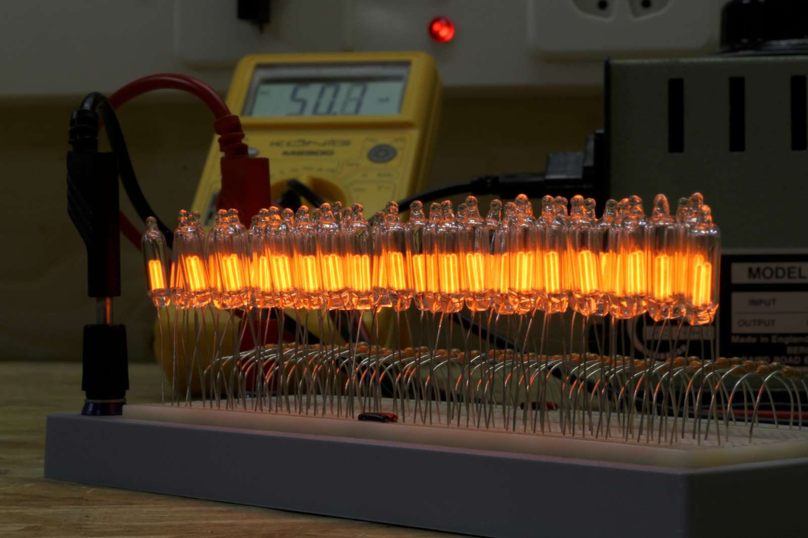
50 glow lamps being aged at twice their nominal current (1 mA
instead of 0.5 mA) for 72 h. (click to enlarge).
If the bulb is operated in DC, it also "polarizes" itself with time. Suppose that the bulb is initially perfectly symmetrical (which is rarely the case anyway), i.e. striking and maintaining voltages are the same in both directions. After a long service using DC, these voltages will no longer be the same.
Even if there are exceptions, the majority of glow lamps are built to be just a lamp, so only little effort is put in keeping their electrical parameter in a tight region. As you can see in the following picture, these two lamps glow very differently, even if they are both new, of the same lot and driven in the same way; no wonder that their electrical characteristics are also different. One has the electrode fully glowing, the other one only partially. I don't know the reason; it's probably due to a different surface finish of the electrodes.
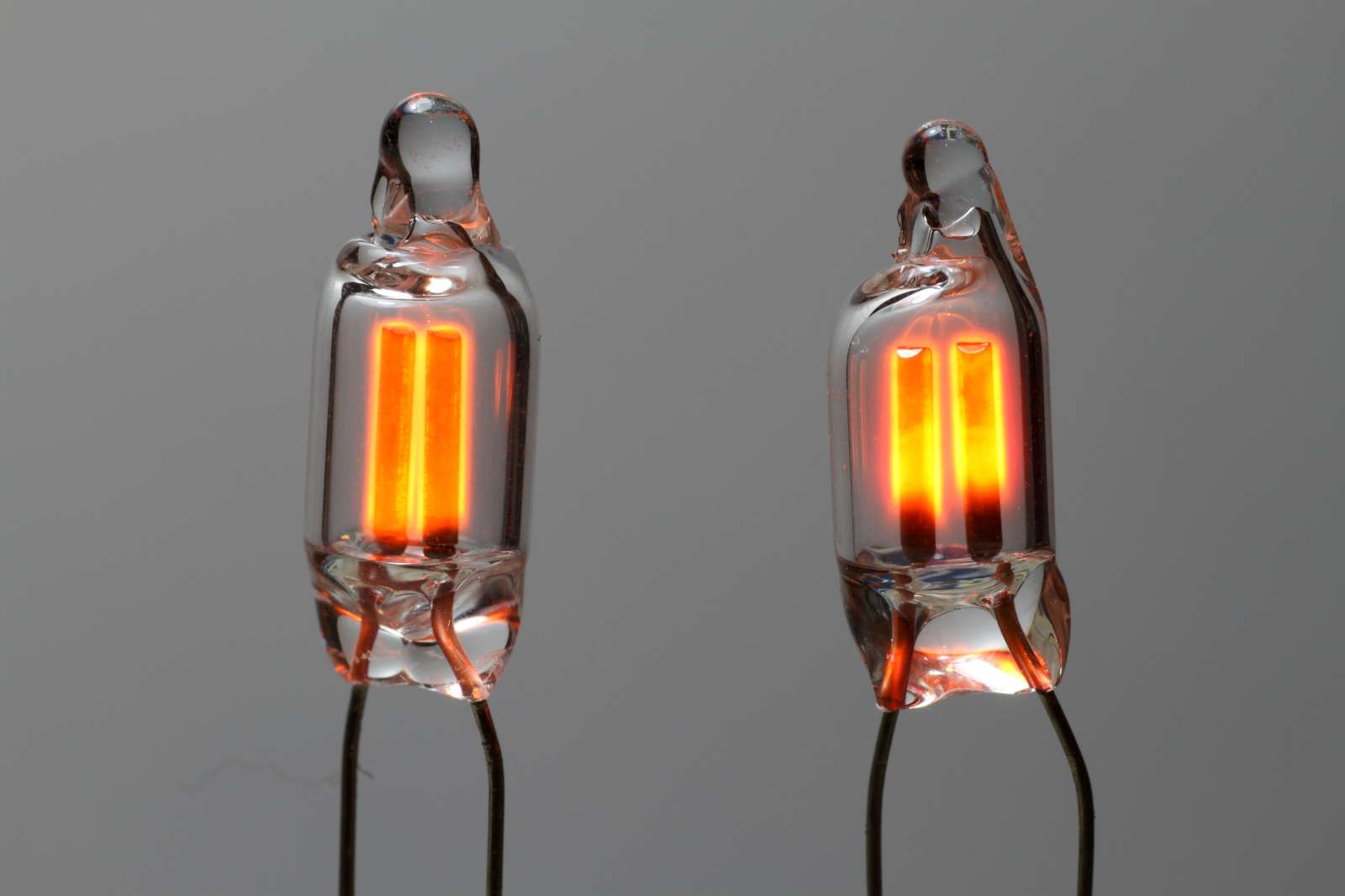
Two brand new and identical lamps (same production lot) driven in the
same conditions (same power supply and ballast resistor value) can glow very
differently. (click to enlarge).
In the following chart is represented the ionization (striking) and the burning voltage of 100 identical glow lamps. They are all new, all of the same lot and all have been aged for 72 h at twice their nominal current. As one can see, the majority follows about the same trend, but not all of them: some lamps have a smaller gap between ionization and burning voltage than others.
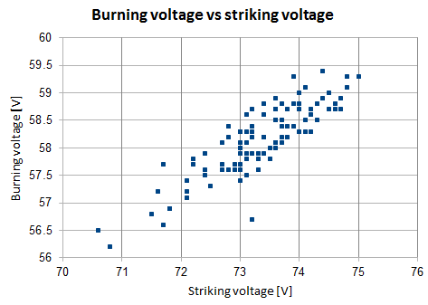
Burning and striking voltage of a lot of 100 new (but aged) glow
lamps.
Neon glow lamps last a very long time: they can burn continuously for decades. If their maximum ratings are not exceeded, they usually fail gradually. With time, part of the metal of the electrodes sputters and accumulates on the inside of the glass wall, coating it with a thin layer of metal. As the metal grows thicker and thicker, the glass becomes less and less transparent: the bulb blackens and gradually becomes less bright.
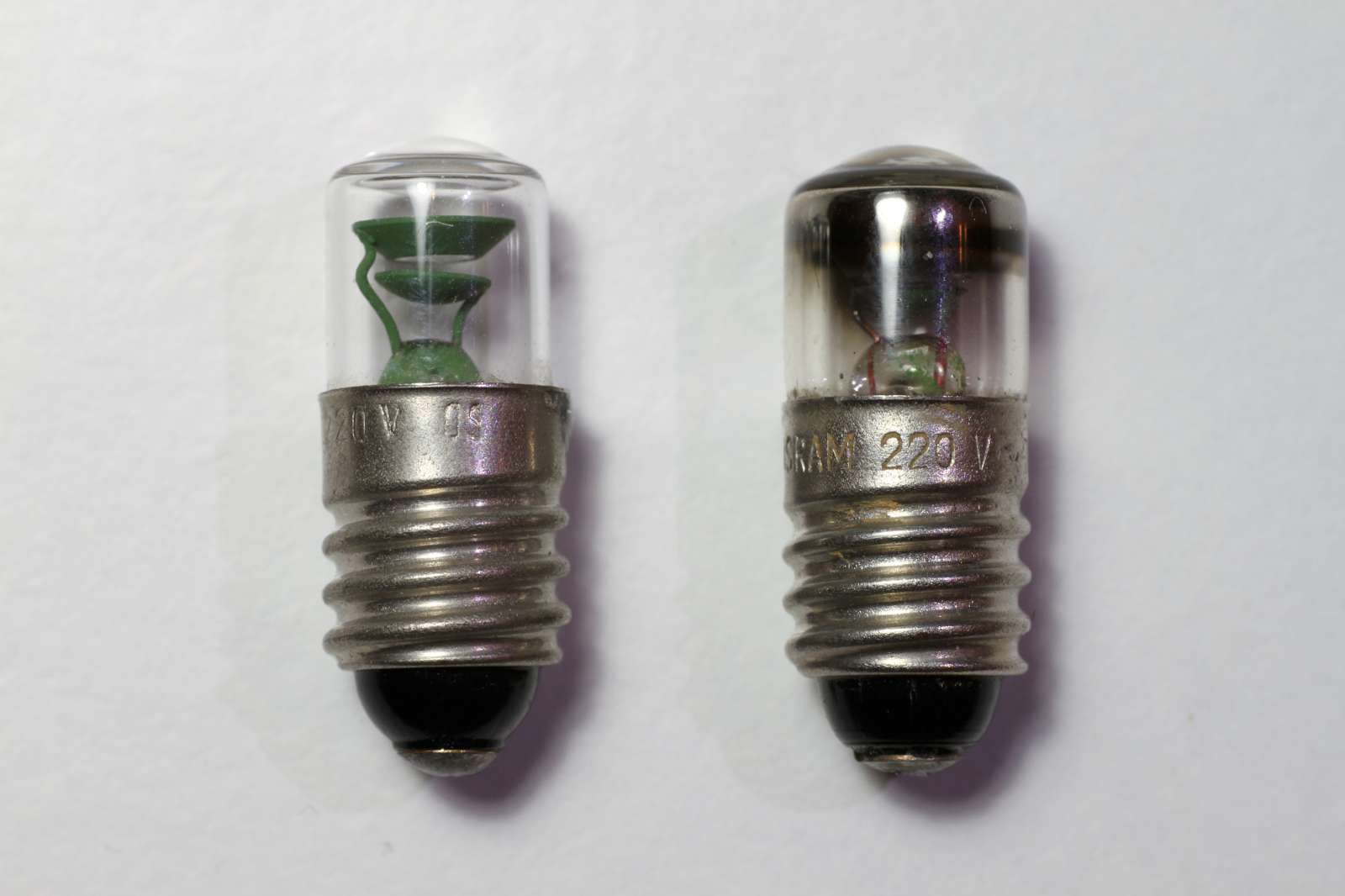
Picture of two glow lamps: the one on the left is new and the one on
the right has several years of service.
(click to enlarge).
If the electrodes are coated, the coating sputters first degrading the electrical characteristics of the lamp: it still burns, but the voltages are higher. The mixture of gasses inside the bulb also degrades with time: the lamp is harder to start and flickers instead of burning continuously.
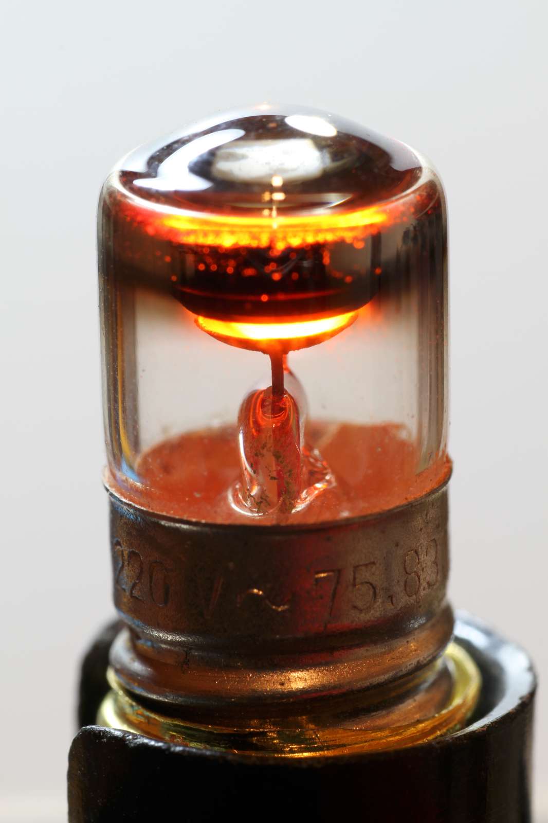
Picture of a glowing lamp after several years of service: it still
glows but the glass is blackened by the metal sputtered off the electrodes.
(click to enlarge).
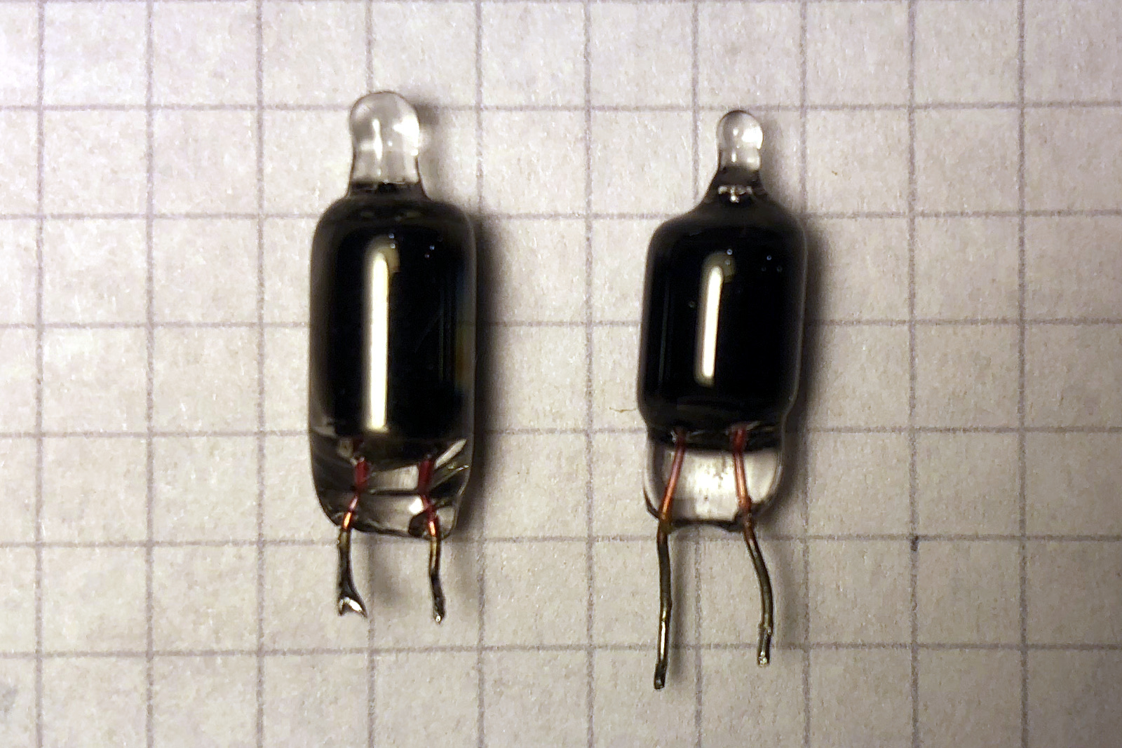
Picture of two glow lamps after several years of service.
The glass is now completely black and the glow cannot be seen anymore, but
electrically they still work.
(click to enlarge).
Glow lamps don't start easily in complete darkness. The lower the ambient light, the more erratic the starting of the lamp becomes: it takes more time and/or requires a higher voltage. To prevent this effect, in some models, krypton-85 is added to the gas mixture. It provides an ionization source, as this gas is radioactive and emits beta particles (electrons). Unfortunately, the half-life of 85Kr is only 10.8 years and its effect doesn't last forever: after a few decades, these bulbs still work, but don't strike as rapidly and reliably as before. This is usually not a problem for a simple indicator lamp, but depending on the application, especially if the lamp is used as an active device in a trigger or counting circuit, replacement may be necessary.
To prevent the dark effect, just adding some external ambient light may do the trick, especially if it contains short wavelengths like blue or violet. For example, mounting blue LEDs shining some continuous light on the inside of the device containing the neon glow lamp(s) is usually all it takes to fix all the issued due to dark effect.
Glow lamps are strongly nonlinear devices and they have a very different behavior if the gas inside is ionized or not. Simply speaking, when the gas is not ionized, the lamp is dark; when the gas is ionized the lamp glows. When the lamp changes from a non-ionized state to an ionized state, the lamp is said to strike or to ionize or to turn on.
When the gas is not ionized the lamp is "off" and behaves almost like an open circuit. To be more precise, only an extremely small current can flow, called dark current, but it's so small that it can be neglected in the majority of the applications. And of course, there is also some stray capacitance, say a few pF.
There are two important threshold voltages that characterize a lamp: the ionizing voltage (also called striking voltage, starting voltage or breakdown voltage) and the maintaining voltage (also called sustaining voltage).
The ionizing voltage is the voltage at which the gas in the lamp ionizes. When this threshold is exceeded, a lamp that was initially off ionizes (or strikes) and switches on. Ionization voltage is usually somewhere between 50 and 100 V and depends on many factors like the type of electrodes, their coating, the composition of the gas, its pressure, the age of the lamp,... just to list a few of them.
The maintaining voltage is the minimum voltage required to keep the gas ionized. Maintaining voltage is always smaller than the ionizing voltage, by about 10 to 20 V. When the lamp is on and the voltage drops below this threshold, the gas loses its ionization and the lamp turns off.
When the lamp is on, the voltage across its terminal is called operating voltage or burning voltage. It's fairly constant with lamp current variations, but the lamp has negative or positive resistance characteristics when on, depending on the current.
When the lamp is glowing but the current is low, only part of the negative electrode is glowing (called normal glow) and the lamp behaves like a negative resistance: increasing the voltage will result in a decrease of the current. When building oscillators, glow lamps are used in this region to take advantage of the negative resistance, but the glow is not very bright. The current is usually below 100 μA, but this depends on the lamp you're using.
When the lamp is glowing but the current is higher, all the surface of the negative electrode is glowing (called abnormal glow) and the lamp behaves like a "normal" resistance: increasing the voltage will also increase the current. When building an indicator light, glow lamps are usually used in this region.
If the lamp is off (non ionized) but has a voltage across its terminals above the maintaining voltage but below the ionizing voltage, it can also be ionized by an external electromagnetic field or a ionizing radiation. It will then stay ionized until the voltage drops below the maintaining voltage.
To have a rough idea on what's going on, I did some measurements on a "regular" neon glow lamp (NE-2 style) and on a green fluorescent glow lamp of about the same size. Let's have a look first at the neon glow lamp.
Picture of the measured neon glow lamp.
The following plot shows the nonlinear characteristics of the neon lamp. Voltage is on the horizontal (X) axis, current is on the vertical (Y) axis. As one can see, the current is almost zero until the voltage reaches the striking voltage (here 70 V), the voltage then suddenly drops to the burning voltage (here 51 V) and only slightly increases with current (it goes from 51 V at 0 mA to 57 V at 3 mA, giving a dynamic resistance of 2 kΩ). Glow lamps are not perfectly symmetric; they are not built to be so: this lamp has a striking voltage of 71 V a marinating voltage of 52 V and a dynamic resistance of 1.6 kΩ if reversed.
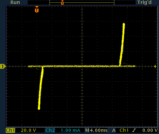
Current as a function of voltage for a neon glow lamp.
Ballast resistor is 100 kΩ
Voltage is on the horizontal axis, current on the vertical one.
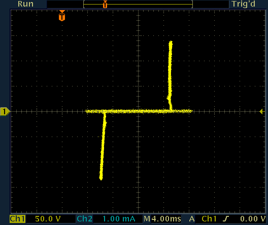
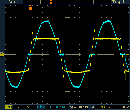
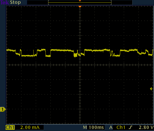
The same data is plotted as a function of time. Here the lamp is connected to the alternating mains voltage (at 50 Hz in this case). Lamp voltage is yellow (CH1) and lamp current is blue (CH2). One can see that after the voltage crosses zero, the current stays zero until the striking voltage is reached; then the voltage suddenly decreases to the burning voltage causing the narrow spikes: the lamp is now lit. The current follows the sinusoidal form of the mains voltage, but the voltage across the lamp only changes slightly. As soon as the voltage drops below the maintaining voltage the current is zero and the lamps switches off. It then remains in this state until the voltage reaches the striking voltage again.
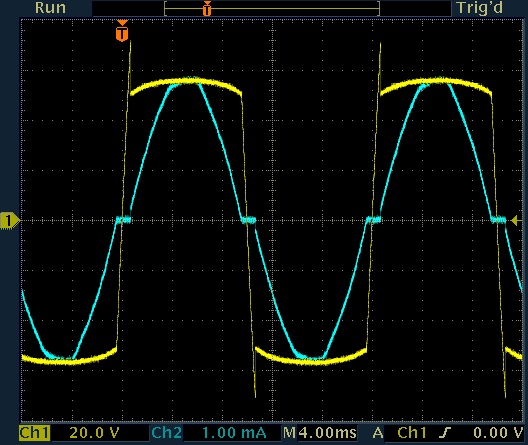
Current and voltage a functions of time for a neon glow lamp.
Ballast resistor is 100 kΩ
Voltage is yellow (CH1) and current is cyan (CH2).
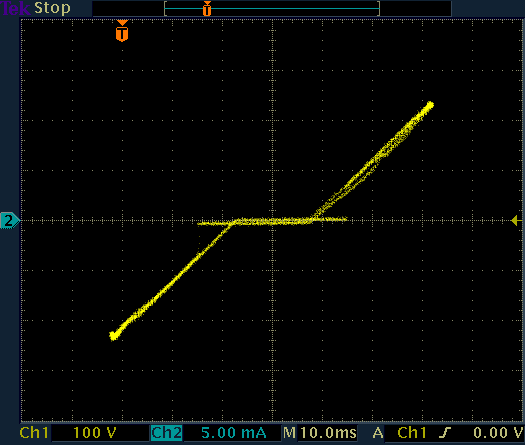
In order to show how the resistance becomes negative for low lamp currents, I tried to increase the ballast resistor from 100 kΩ to 4.7 MΩ. The good news is that the lamp oscillates (see below) proving that its dynamic resistance is indeed negative, but because of the oscillations it doesn't clearly appear on the plots.
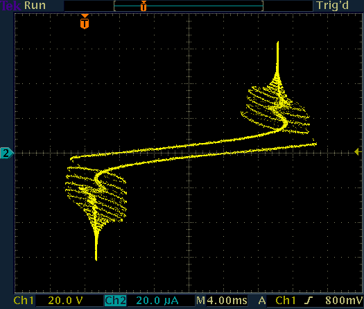
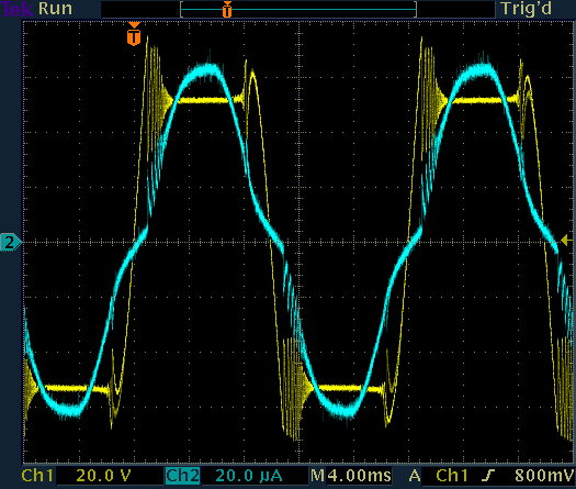
Current as a function of voltage and as functions of time for a neon
glow lamp driven with a high value ballast resistor (4.7 MΩ).
Unfortunately, this is not the same exact lamp as before, so threshold
voltages are a bit different.
When the current is low, the lamp oscillates, indicating negative resistance.
On the left image, voltage is on the horizontal axis and current on the
vertical one; on the right image voltage is yellow (CH1) and current is cyan
(CH2).
To see if green fluorescent glow lamps behaves similarly, let's now have a look at one of those. They work on the same principle, but have a different mixture of gasses inside.
Picture of the measured green flour glow lamp.
The following plots show the same measures as before but for a green glow lamp. Here the striking voltage is 107 V (102 V when reversed), the maintaining voltage is 57 V (64 V) and the dynamic resistance is 2 kΩ (3.2 kΩ).
Current as a function of voltage and as functions of time for a green
fluorescent glow lamp.
Ballast resistor is 100 kΩ
On the left image, voltage is on the horizontal axis and current on the
vertical one; on the right image voltage is yellow (CH1) and current is cyan
(CH2).
If you want to do similar measurements yourself with your oscilloscope, an insulation transformer and a suitable high voltage probes are a must.
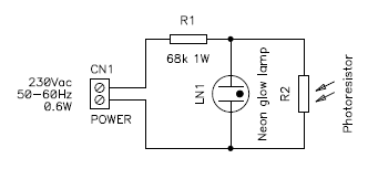
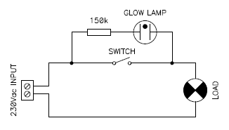
This is simplest and most common application for neon glow lamps: simply a lamp that glows when the mains voltage is present. This will tell if the mains voltage is present or if an appliance is switched on.
The circuit is extremely simple: the glow lamp is connected in series with a suitable resistor and connected to the mains voltage. The resistor value depends on the type of lamp and the nominal mains voltage but it's really not critical: consider about 150 kΩ for 230 VAC and about 68 kΩ for 120 VAC lines. The current in the lamp will be about 1 mA.
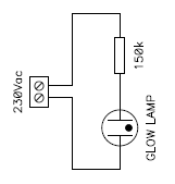
Circuit diagram of the main voltage monitor.
Calculating the resistor value exactly is quite complicated as the lamp characteristic is nonlinear and current is not sinusoidal, but it's not worth the effort: the current in the lamp is really not critical, just measure the current (with a true-RMS multimeter) if you're worried about it, but it's not really important, having 0.5 or 2 mA will not make much difference. Usually the power dissipated in the resistor is quite low and a single 0.25 W model is enough, a 0.5 W is a more conservative choice.
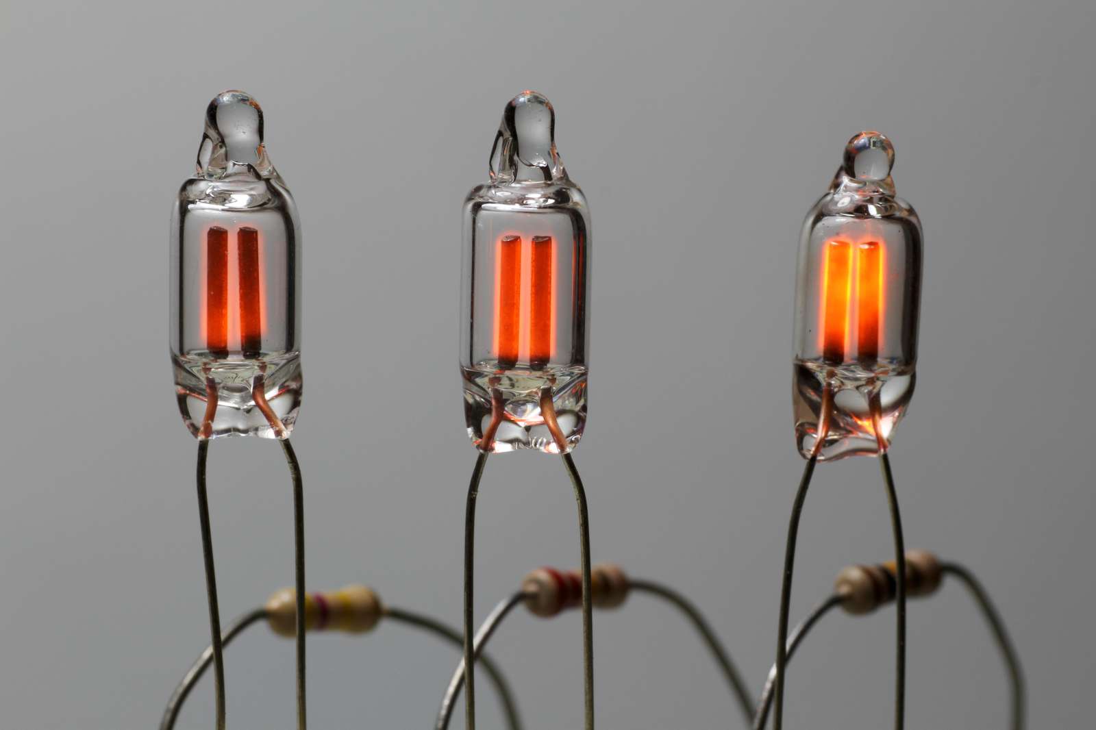
Three similar glow lamps running at different currents: 350 μA
(left), 700 μA (center) and 1.6 mA (right). (click to enlarge).
If you want a universal pilot light, which can work from 120 V up to 400 V, use a higher resistor value; say 470 kΩ or 1 MΩ rated for 0.5 W. Not all resistors are designed to deal with the peak line voltage: if it exceeds their absolute maximum rating, you can connect two or more smaller resistors in series.
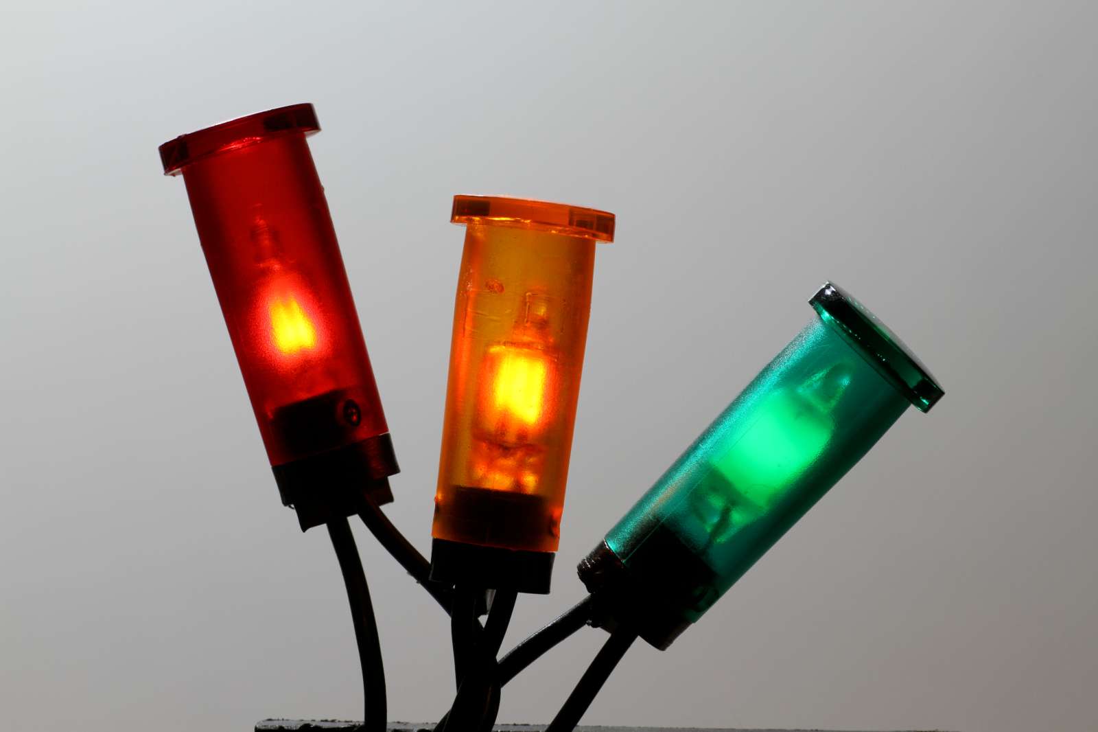
Three mains voltage indicator lamps with integrated ballast resistor.
The red and orange lamps use a true neon glow lamp while the green one is of
the fluorescent type. (click to enlarge).
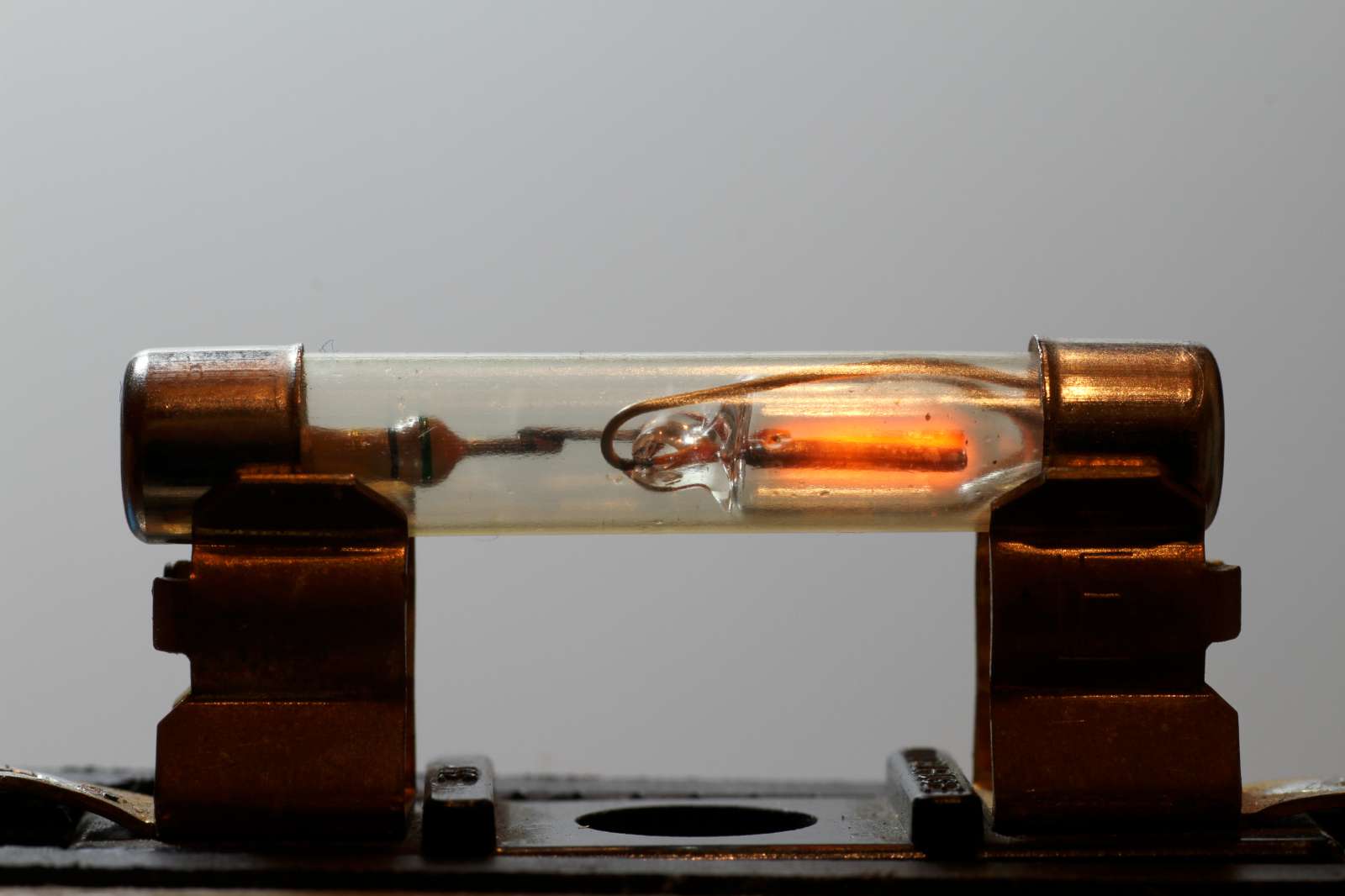
This glow lamp is in a fuse-like glass package and its ballast
resistor is clearly visible.
This particular lamp doesn't fit perfectly in the fuse holder I have, so for
this picture, I just laid it on it. (click to enlarge).
Because of their ability to run on mains voltages with just a ballast resistor, their low current consumption and their low light output, neon glow lamps are (were) widely used as night lights, i.e. these little lamps you plug into an AC outlet to make the night less dark in a kid bedroom. Now, this application is identical to the mains voltage indicator lights we just discussed, but over the years I stumbled into some curious circuits that deserve their place here.
By simply adding a photoresistor in parallel with the glow lamp, it's possible to make a very simple and crude night light that turns off during the day. The photoresistor is placed in such a way that it's not directly affected by the light emitted by the glow lamp, but it can still see the ambient light. The ballast resistor and the photoresistor act as a voltage divider. When there is daylight in the room, the resistance of the photoresistor is low and the voltage across the lamp drops to a value low enough to prevent it from striking.
Circuit diagram of the nighttime only night light.
I don't recommend this circuit because it dissipates more power when the lamp is off than when it's on; still I find it interesting because of its simplicity. It does the job with just one more photoresistor and I couldn't think of any simpler circuit to do the same thing. At the end, the power used by this device is negligible, but still it would be "better" in terms of efficiency to leave the lamp constantly on than by turning it off by shunting it with a photoresistor.
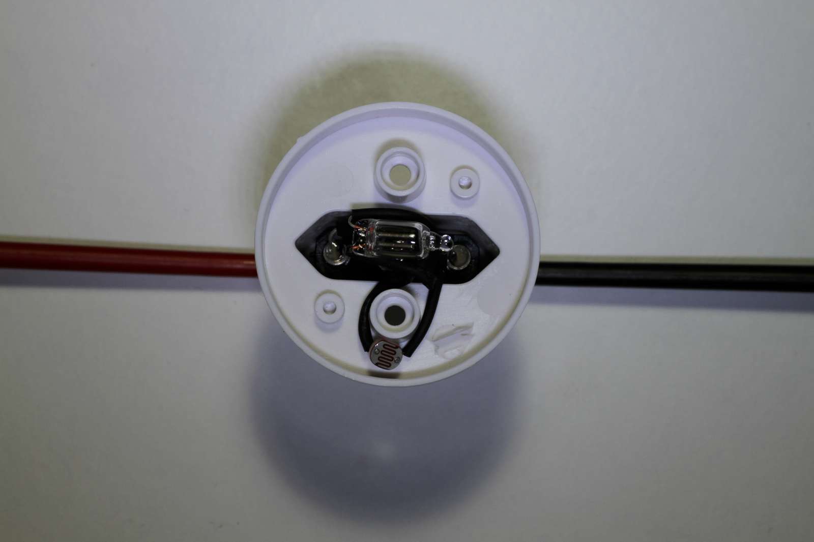
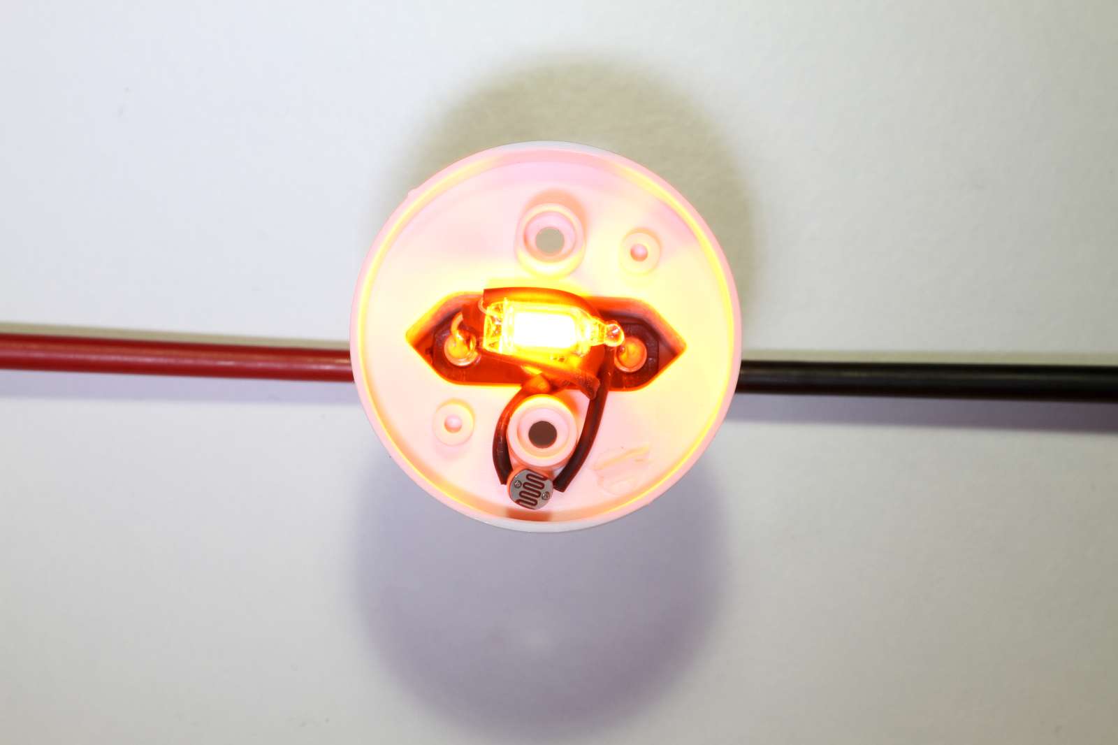
Two pictures of this nighttime only night light, "off" on
the left and "on" on the right.
Because of the different exposures on the two pictures, it's not possible to
appreciate that ambient light is a lot darker when the lamp is on.
(click to enlarge).
The following green night light is interesting because of the shape of this glow lamp that is a little fluorescent tube, of about Ø 9 mm × 50 mm. It has cold cathodes and is connected as a normal neon glow lamp with just a series 330 kΩ resistor and no starting circuit, but its shape is much bigger. Here the glow comes from the gas between the electrodes and not by the volume immediately surrounding them. It's a completely different kind of glow: here the part of the discharge that is glowing is called the positive column like in common hot cathode fluorescent tubes, while in normal neon glow lamps it's called cathode glow.
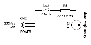
Circuit diagram of this green tube night light.
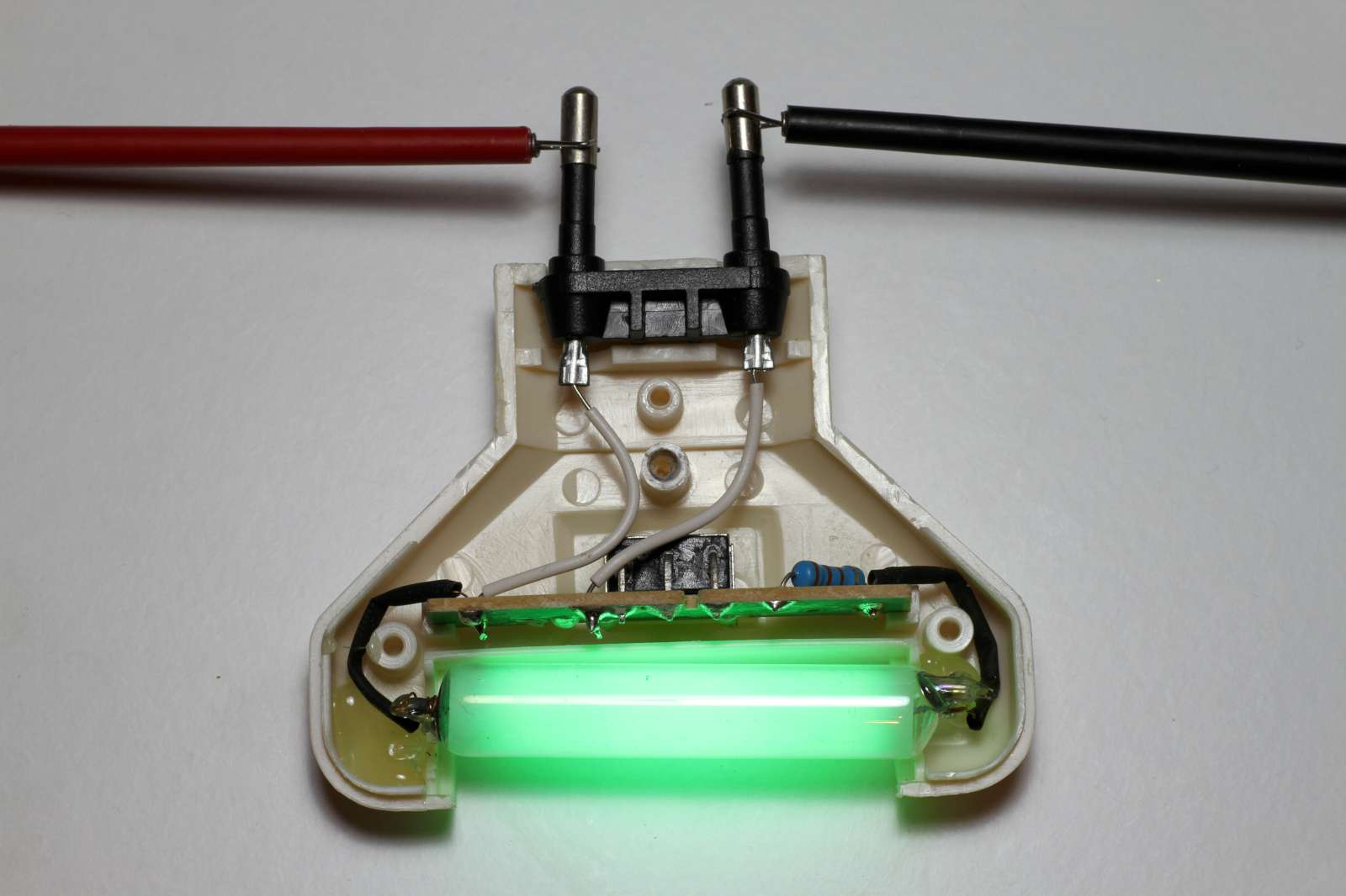
Picture of the green tube night light. (click to enlarge).
Unfortunately I don't have any specific technical information on this lamp. But I did measure its spectrum and I can tell that it contains mercury, because its typicial emissions lines at 436, 546 and 577 nm are clearly visible. Usually, there is also another noble gas in the lamp to form a Penning mixture, but here it could not be observed. The bell-shaped emission at 523 nm is due to the fluorescent coating on the tube wall that converts the UV light emitted by the mercury into visible green light.
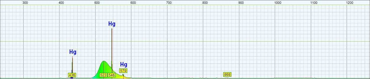
Spectrum of the light emitted by this green night light.
The wavelength in nm is on the horizontal axis and the amplitude in arbitrary
units is on the vertical one.
The following white night light is even more interesting as it has separated starting electrodes. Here the lamp is also in a form of a small tube about Ø 9 mm × 50 mm, but each side has 3 terminals: two of which are connected together and one is alone. The tube has cold cathodes: the terminals connected together internally are just the main electrodes, but they are not heated by a current, they are not a filament. But to start the lamp, additional starting (priming) electrodes are placed very close to the main electrodes. The starting electrodes are connected to the opposite main electrodes with two 68 kΩ resistors: this is enough to ionize the gas locally as in a common glow lamp. Once ionized, the discharge moves between the main electrodes and shunts the two starting resistors. This is a nice trick to strike a lamp that would normally require a little more than the peak mains voltage to ionize. Also in this tube the glow comes from the gas between the electrodes and not by the volume immediately surrounding them.
Here, the ballast is a 470 nF capacitor. The inrush current is limited by a 390 Ω resistor and the 1 MΩ one acts as bleeder resistor to discharge the capacitor when the device is unplugged.
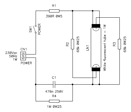
Circuit diagram of this white tube night light with its ballast and
starting circuit.
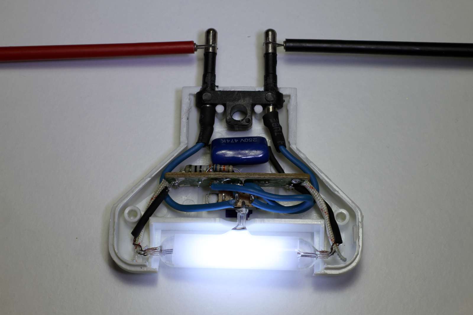
Picture of the white tube night light. (click to enlarge).
Unfortunately I don't have any specific technical information on this lamp, neither. But again, I measured its spectrum and found that it also contains mercury, as its typical emission lines at 436, 546 and 577 nm are clearly visible, but we also see presence of neon (peaks at 610, 838 and 865 nm) and argon (peaks at 764, 810, 842 and 867 nm) clearly showing the Penning mixture of this lamp. Again, with the low precision of my spectrometer I cannot really tell if the measured emissions at 840 and 868 nm are due to neon (838 and 865 nm) or to argon (842 and 867 ), but the presence of both gasses is already confirmed by other peaks.
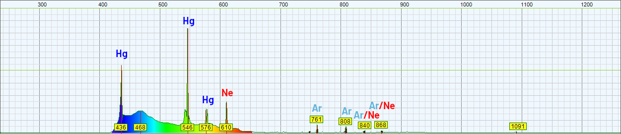
Spectrum of the light emitted by this white night light.
The wavelength in nm is on the horizontal axis and the amplitude in arbitrary
units is on the vertical one.
Neon glow lamps are widely used as switch orientation lights, just to illuminate the switch when the light is off so that it can be easily found in the dark. The trick is simply to install a neon glow lamp (with its ballast resistor) in parallel with the switch: when the switch is open, the lamp is in series with the load and glows. The circuit is presented in the figure below; again, not a rocket science circuit, but it's so widely used that it deserves mentioning.
Circuit diagram of the switch orientation light.
Neon glow lamps only use a little current, so the load has significantly lower impedance than the ballast resistor effectively closing the circuit while the low current of the lamp is not enough to power the load that stays off. When the switch is closed, the load is regularly switched on and the lamp is short circuited.
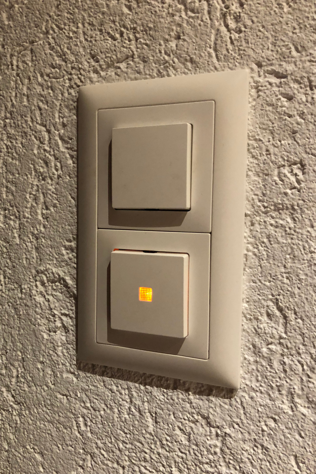
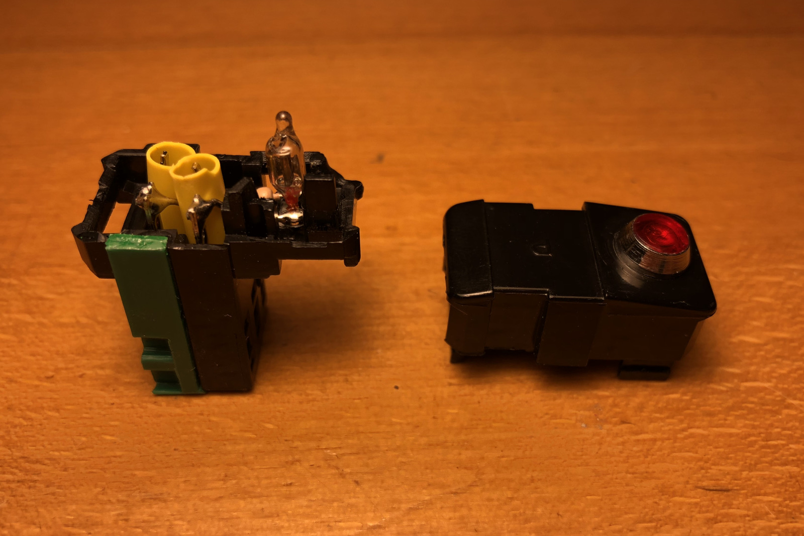
This illuminated switch contains a small neon glow lamp (and ballast
resistor) in parallel with it.
It only glows when the light is off.
(click to enlarge).
Any load which draws much more power than the lamp will do the trick: a lamp, a motor, a relay, a timer... The condition for this to work is that the load stays off with the small current of the glow lamp; it's usually the case with most loads, but some sensitive electronic devices such as LED or CCFL lamps may not like this and try to start from time to time, producing annoying flashes. If this happens, one could add a resistive load in parallel to the actual load, such as a small filament light bulb, or drive the load though an electromagnetic relay (contactor).
We have seen before that neon glow lamps require a minimum voltage to strike and keep burning. We can take advantage of this characteristic to build a simple (analog) telephone ring monitor, i.e. a lamp that blinks every time the phone rings. It's important to specify that this only works with old analog phone lines; if you have a modern digital phone line, it will not work.
Remark: in many countries connecting non-certified devices such as this one to a telephone line is not allowed. This application is only presented for didactic purposes.
The analog phone line has an idle (on-hook) voltage typically slightly less than 50 VDC which drops to about 10 VDC when the phone is off-hook. This is not enough to strike a glow lamp. But when the phone rings, an AC voltage of about 150 VAC is superposed to the line, which is more than enough to ionize a glow lamp. The low current consumption of glow lamps is a desirable feature in this case, because it doesn't overload the phone line.
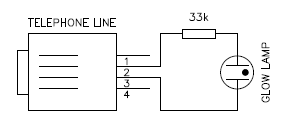
Circuit diagram of the phone ring monitor shown here with an RJ11
connector.
Not all countries have the same phone standards and your voltages may differ, but these values are typical. If the lamp keeps glowing after the ringer, the maintaining voltage of the lamp is too low (lower than the telephone idle voltage). To solve this problem just try a different glow lamp or connect two glow lamps in series.
The circuit diagram is the same as the mains voltage indicator light, only the resistor has been sized for the lower voltage. Such a simple circuit can be very easily installed inside a (Swiss) phone plug.
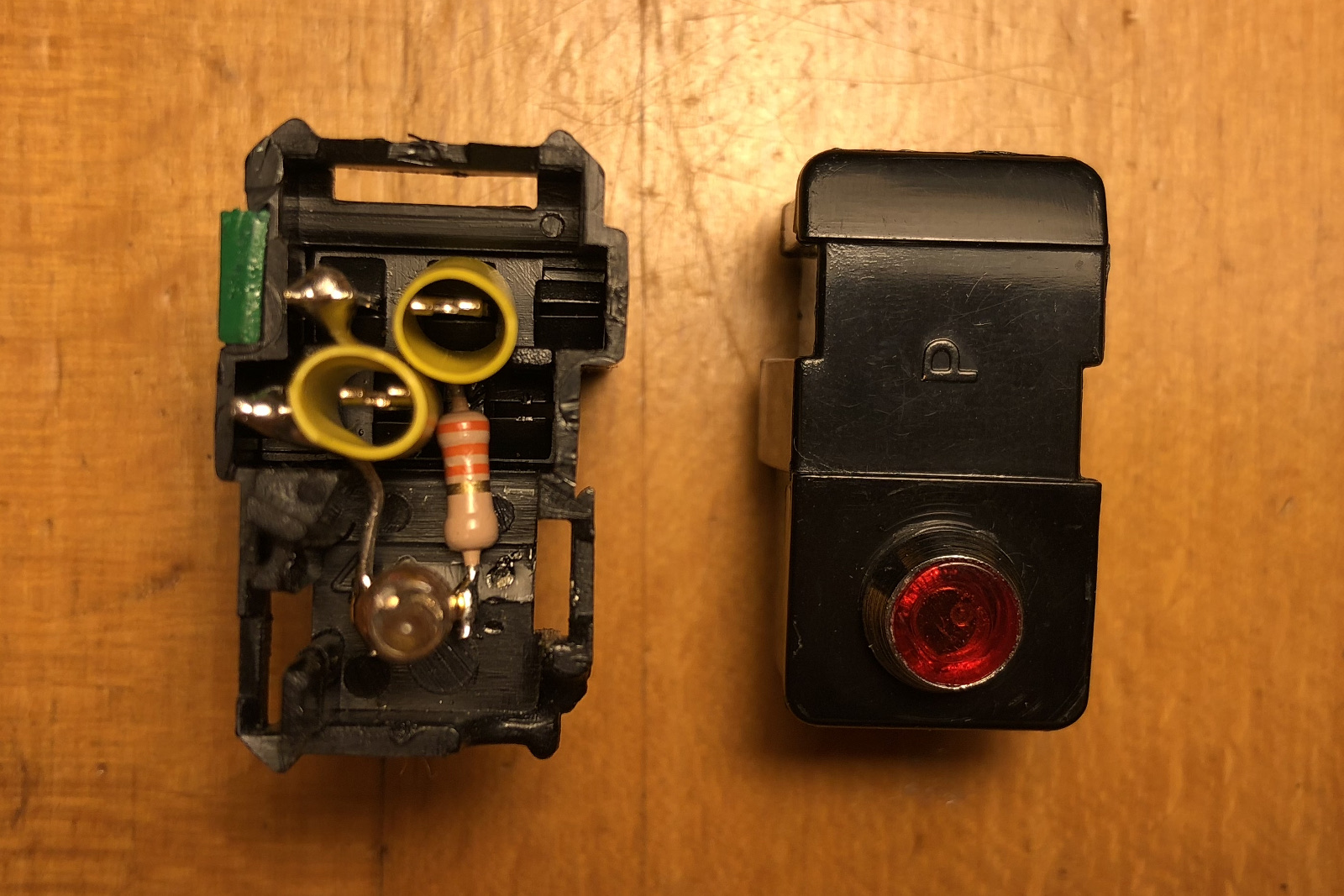
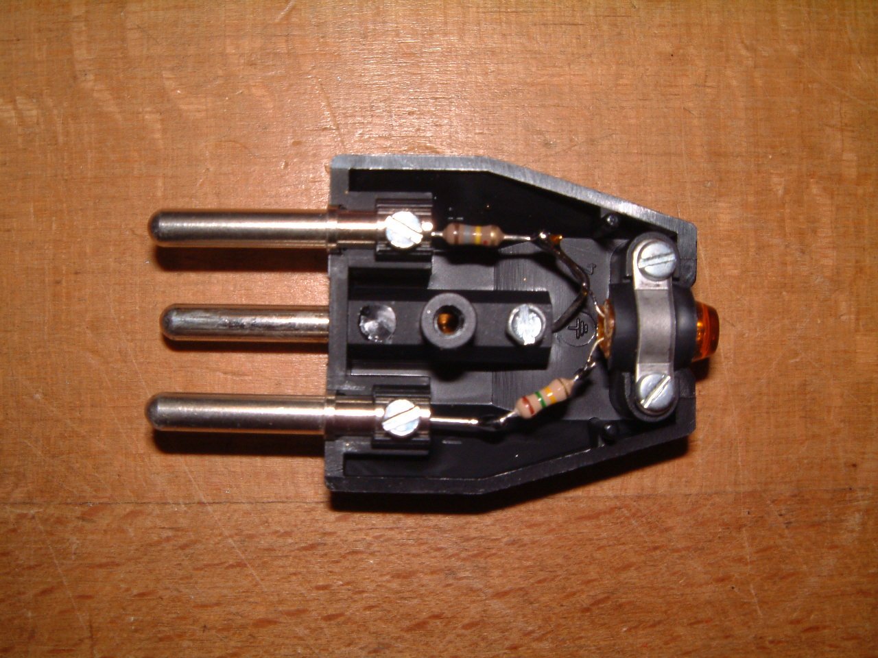
Two pictures of the phone ring monitor showing how it's assembled
inside a plug.
(click to enlarge).
The mains tester screwdriver is another typical application of neon glow lamps, because of their ability to glow with very low currents. It's an old tool used by electricians to test if a wire is live at mains potential. It consists in a screwdriver with an insulated handle. Inside the handle, there is a neon glow lamp and a high value series resistor, around 1 MΩ. One side is connected to the shaft, the other to a metal ring or clip on the handle. The user touches the clip with his hand and the conductor under test with the tip of the shaft. If the wire is live, a very small current will flow through the lamp, the resistor and the operator body closing the circuit thorough capacitive or resistive coupling to the ground. If the lamp glows, the conductor is live. The resistance has a very high value to keep the current at a safe value, say 100 to 200 μA, so that it cannot be felt by the user.
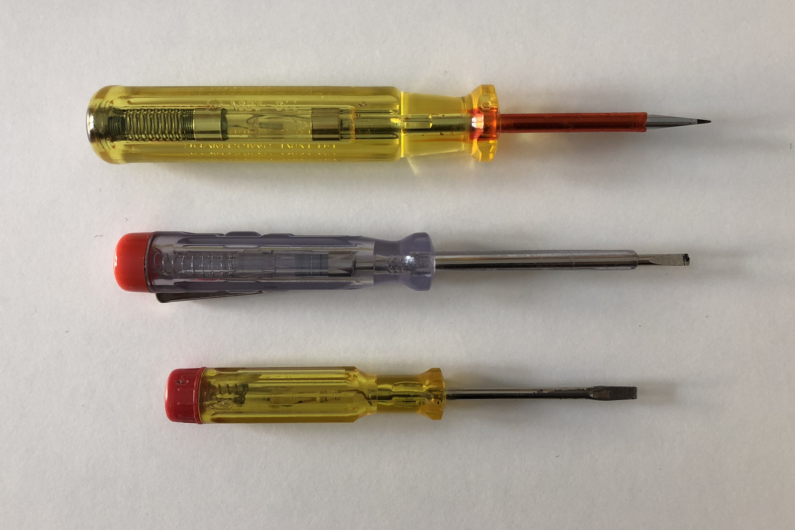
Picture of three mains tester screwdrivers.
The bottom one is an old one and its shaft is not insulated.
(click to enlarge).
These tools are not extremely safe to modern standards because they require a direct contact with the circuit under test one side and with the operator body on the other. A failure in the resistor could expose the user to electrical shockks, especially if the screwdriver is wet. Modern testers have the screwdriver shaft insulated by a thick plastic tube that leaves only the tip exposed. Another important point is that the glow is not very bright and is difficult to see in direct sunlight. The brightness also depends on how the user closes the circuit: the lamp will glow stronger if you're in a concrete basement laid against a wall than if you are standing on a wooden ladder on a roof as the capacitance between your body and ground is not the same. This may lead to some wrong conclusion. This being said, I've been happily using this kind of testers for decades and I'm still doing fine; I just treat them with the respect they deserve. Even if the tester told you that a wire is not live, it's still good practice to ground any potentially live conductor before touching it.
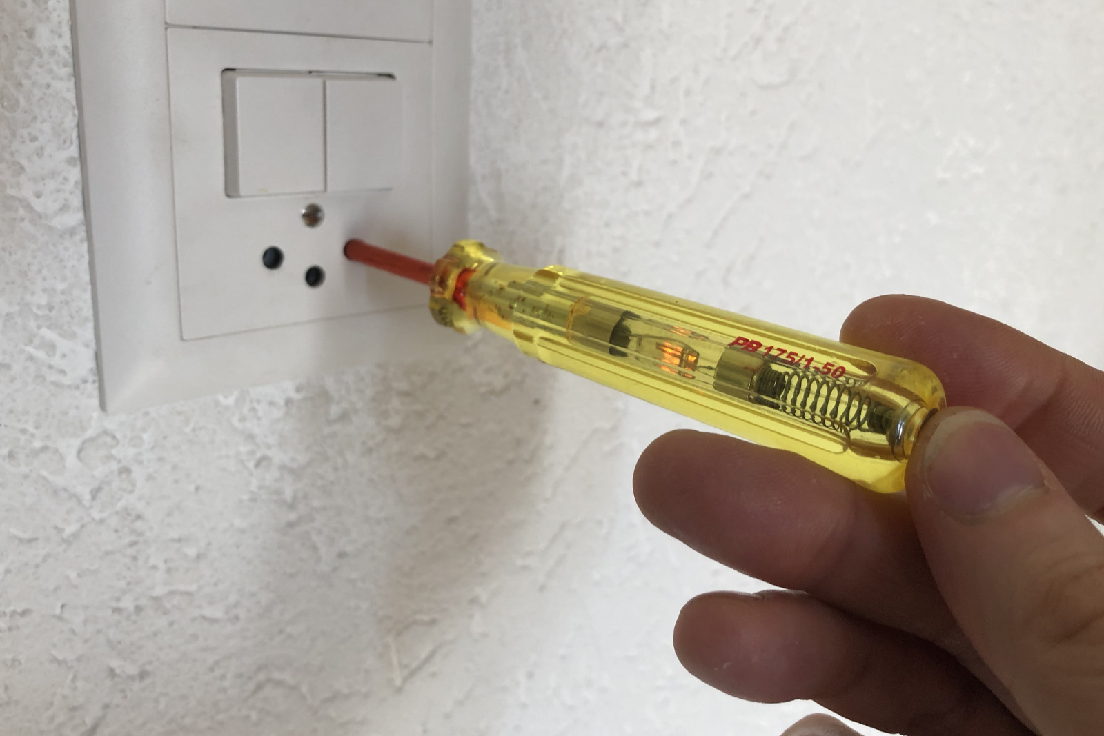
Picture of a mains test screwdriver in action.
Note how the user touches the back ring to close the circuit.
(click to enlarge).
With only a neon glow lamp and two resistors it's possible to build a useful tool that checks if the earth wire of an AC power outlet is correctly connected.
There are several earthing systems that vary from country to country, but usually the neutral (N) conductor is connected to the protective earth (PE) conductor at the transformer (or house entry point) and both conductors run separately to the various outlets (TN-S or TN-C-S systems). They are two separate wires, but they are connected together.
The idea is that this connection between earth and neutral short circuits the lamp preventing it from glowing. If the earth wire (PE) is not connected or if the live (P) and neutral (N) wires are inverted, the full voltage would appear across the lamp that would glow indicating the presence of a problem.
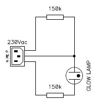
Circuit diagram of the earth checker.
The reason there are two 150 kΩ resistors instead of just one, is to prevent short circuits or overloading the lamp if the wires are crossed. You can use this circuit on 120 VAC mains by reducing the two resistors to about 68 kΩ.
If the earthing system of your installation doesn't have a direct connection between the neutral and the earthing conductor (TT or IT system) this circuit will probably not work.
Please keep in mind that this simple circuit cannot detect all wrong wring connections: for example if the neutral wire is not connected but the live one is, the lamp can't glow even if there is a problem with the earth wire. Still, it's a quick and easy tool to detect most wrong wirings.
Picture of the earth checker. (click to enlarge).
This circuit is extremely simple and can be built directly into a mains plug as shown in the above picture. In the one I built, the lamp is located where the cable is usually mounted and that is actually in a very convenient location.
The previous circuit can be improved by adding two more neon lamps and a bunch of Zener diodes. The circuit is a little bit more complex but more versatile.
As before, we assume that the earthing system you're using has the neutral conductor (N) and the protective earth conductor (PE) connected together at the transformer (TN-S or TN-C-S systems). It won't probably not work (or perform poorly) for TT and IT systems where there is no direct connection between earth and neutral.
So the neutral and the earth conductors are usually at the same electrical potential, the two 150 kΩ resistors are in parallel and all three lamps glow. If one connection is missing or two wires are inverted, these resistors will form a voltage divider that halves the mains voltage on one or more lamps that will not glow. The groups of two Zener diodes connected back to back are there to avoid that the lamps glow with about half of the main voltage.
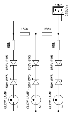
Circuit diagram of the outlet tester.
Making this circuit work for 120 VAC mains is a bit tricky, as there is less margin between the lamp striking voltage and half the peak mains voltage. I didn't test it, but I think that simply using 43 V Zener diodes instead of 150 V ones should do the trick. Resistor values should be ok, at least for a starting point, but you may need do decrease them if the bulbs are too dim. In this case decrease all of them by about the same percentage so that the ratios are conserved. This assumes light bulbs that strike at 70 V and burn at 55 V; if your bulbs are considerably different, you many need different Zener voltages or different lamps.
This circuit is able to detect more wrong wirings than the previous one. Still, it cannot detect if neutral and earth are inverted, as these two wires are at the same potential, only the color of their insulation is different. The meaning of the three lamps is the following:
| Lamp 1 | Lamp 2 | Lamp 3 | Meaning |
| ON | ON | ON | Ok |
| ON | ON | off | No Earth |
| ON | off | off | Live - Neutral inverted |
| off | ON | ON | No Neutral |
| off | off | ON | Live - Earth inverted |
| off | off | off | No Live |
This circuit is a little too complex to fit inside an AC mains plug, so I built it inside a small plastic box and connected to the plug with a short cable, as you can see in the picture below. I also printed the table with the meaning of the lamps for quick reference.
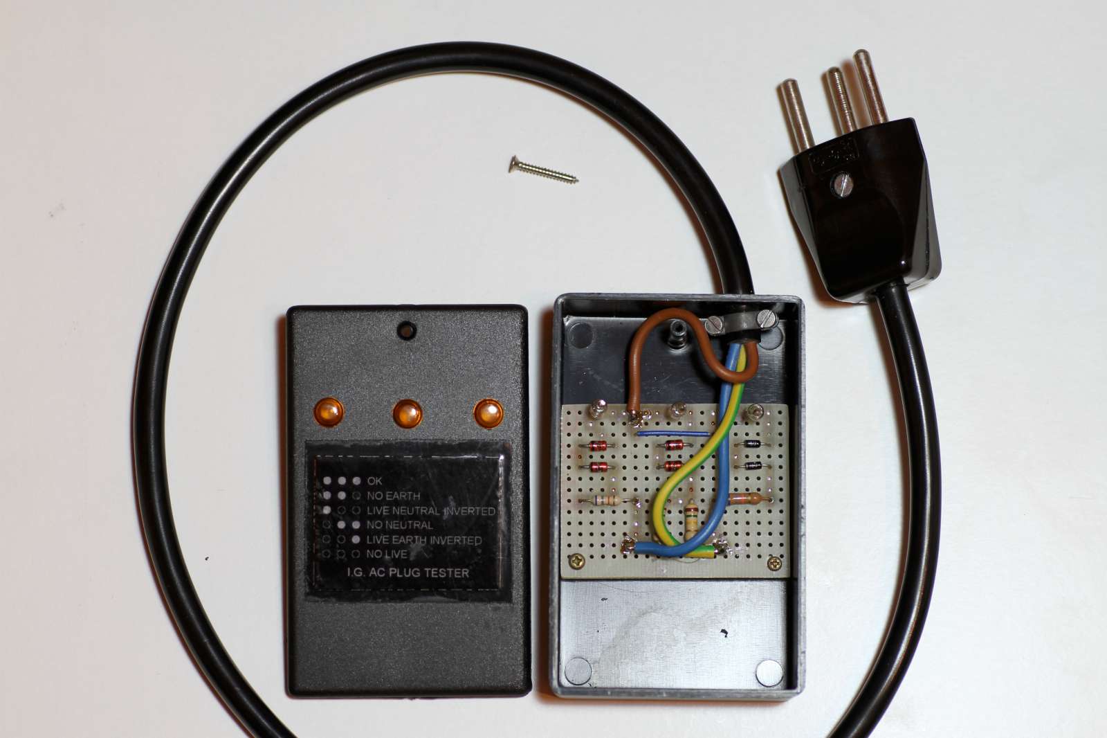
Picture of the tester. (click to enlarge).
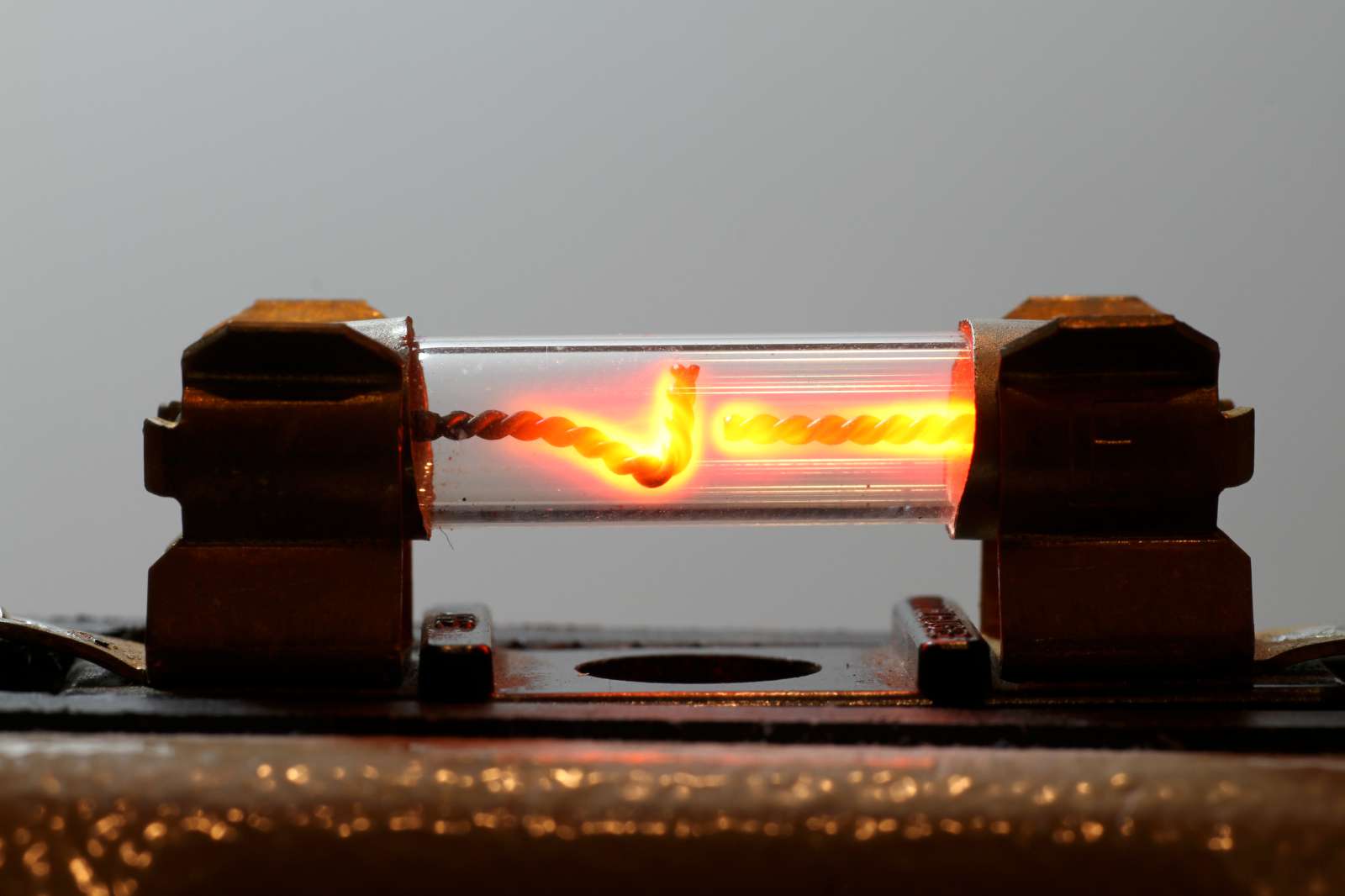
Detecting if a gas or oil burner is actually burning is tricky to do, but can be very useful, for example to shut off the fuel supply if the flame goes off. A furnace is a tough environment: a photodiode can detect the light emitted by the flame, but it may not resist the high temperature. Or soot can accumulate on the diode preventing it from seeing the flame. Some flames, like the ones produces by burning gas, emit very little visible light and can better be detected with UV photodiodes which are delicate and expensive. A thermocouple could reliably measure the temperature inside the furnace, but because of thermal inertia, may take several seconds to a few minutes to react.
A neon glow lamp can reliably detect and show the presence of a flame by running a current through it. And the circuit is really simple: all you need is a little more than a neon glow lamp and a tungsten electrode.
Flames are made of plasma: they contain ionized particles that can conduct electricity. An electrode in the flame will close the circuit with the burner only when a flame is burning on it. Of course, you need an electrode that won't burn and won't melt, like a tungsten one. Fortunately they are easy to find: gas barbecue igniter electrodes are readily available, cheap, made of tungsten and insulated with a heat-resistant ceramic mount: they work great for this application. For safety reasons the burner should be grounded. The circuit is represented in the following figure:
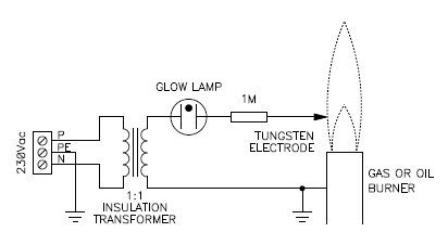
Circuit diagram of the flame detector.
The insulation transformer is a good idea, because directly connecting the electrode with the live conductor of your mains supply is dangerous, should someone touch it. The 1 MΩ resistor is another good idea to limit the current to a safe value in case of an accidental short circuit of the electrode to the ground.
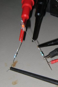
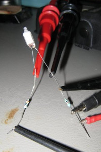
In the following picture, you can see a test setup I did with a propane torch. The torch is connected to ground with the black alligator clip on the left, the tungsten electrode is in the flame and glows red because of the heat and the neon glow lamp is clearly glowing. The two alligator clips in the center and on the right are just for mechanical support and have no electrical connection.
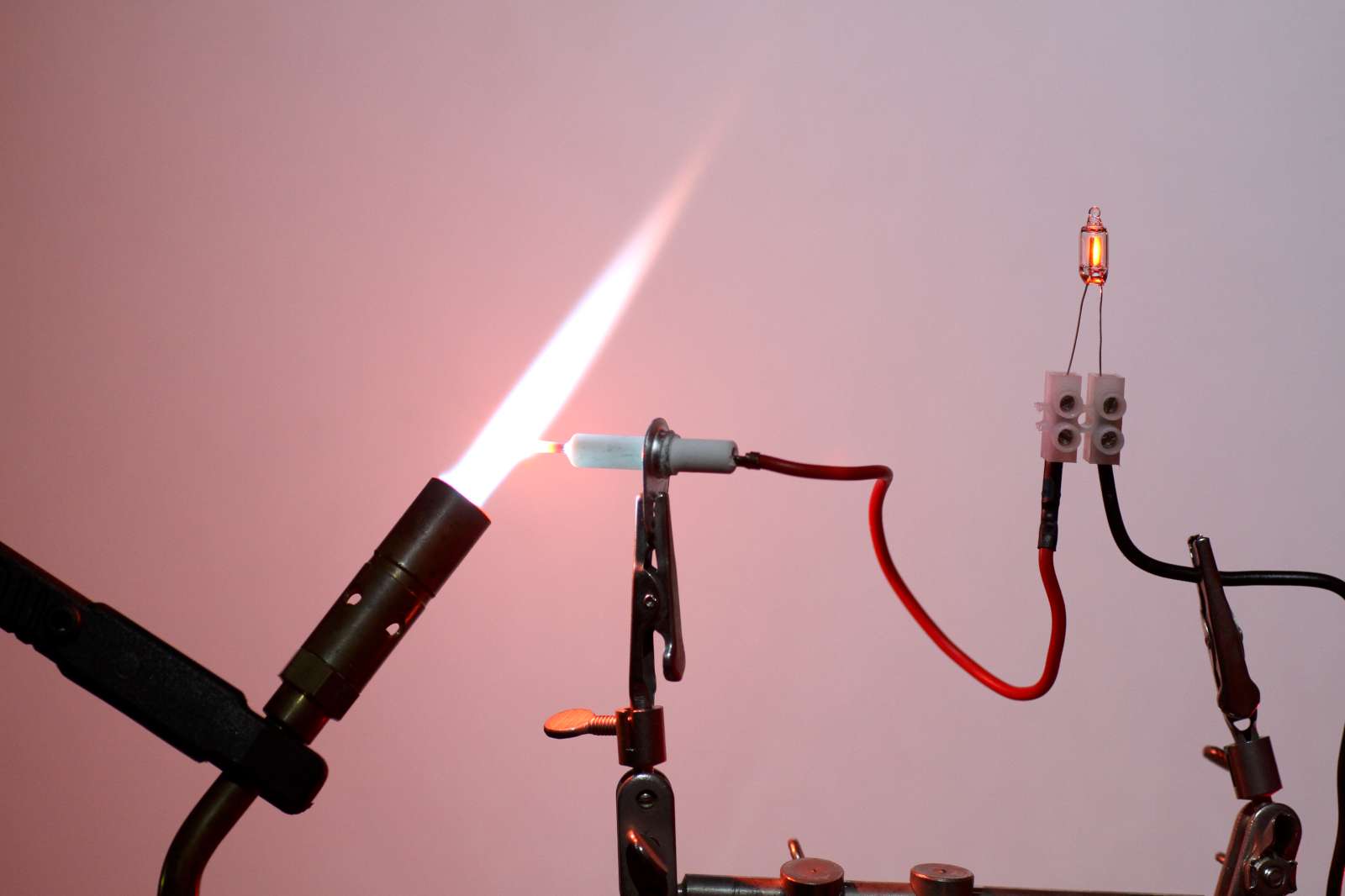
A neon lamp is glowing with the current flowing through the flame of a
propane torch.
Because of the long exposure, both the flame and the lamp look brighter than
what they actually are.
(click to enlarge).
With the flame on, I measured a current of about 10 μA with a mains voltage of 230 VAC: this is more than enough to make the neon lamp glow. It's not very bright, but it glows. If a useful (digital) signal is needed, one can create a simple optocoupler by putting a photodiode or a photoresistor next to the glow lamp and shield them from ambient light in a black enclosure. This allows driving a microcontroller or a logic circuit. The nice thing is that the reaction of the lamp is almost immediate: you shut off the flame and the lamp shuts off, you light the flame and the lamps starts glowing, regardless if the electrode is hot or not.
I also remarked that the flame works as a diode and conducts more current when the furnace is positive and the tungsten electrode negative: as you can see in the picture the right electrode of the glow lamp is brighter, indicating that more current is flowing left to right. I don't know why this phenomenon happens and if it's related to thermoionic emission of the hot tungsten electrode.
Neon glow lamps and diacs (also called trigger diodes) have very similar electrical characteristics. In some cases, it's possible to replace a diac with a glow lamp. But let's first have a look at a diac and at its current vs voltage curve.
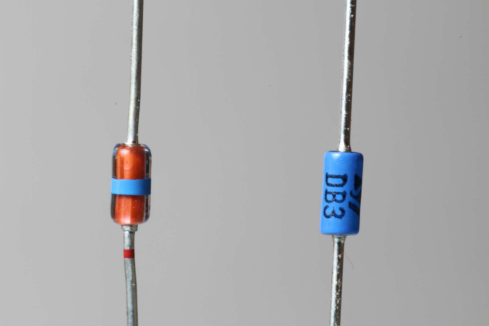
Picture of two DB3 diacs from two different manufacturers.
The one measured here is the one on the right manufactured by ST.
(click to enlarge).
So, I hooked up a diac to a curve tracer in the same way I did it for neon glow lamps. In the following plot, one can see how this device behaves. The voltage is on the horizontal axis and the current is on the vertical one. By comparing this with the characteristic of a neon glow lamp measured before, one can see how similar they are.
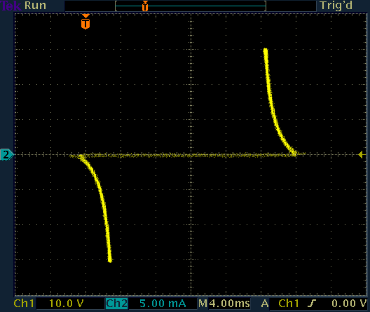
Current as a function of voltage for a DB3 diac.
Voltage is on the horizontal axis, current on the vertical one.
Diacs trigger around 30 V, which is about half of the ionization voltage of a glow lamp. Diacs are more symmetric and do not snap as abruptly as glow lamps do.
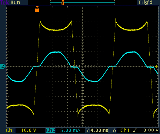
Current and voltage a functions of time for a DB3 diac.
Voltage is yellow (CH1) and current is cyan (CH2).
Of course, diacs are designed to trigger on precise voltages and to be symmetric, but it's sometimes possible to replace a diac with a glow lamp and still have a working circuit. A diac is definitely a better choice, but if you're stuck on a desert island with no diacs and plenty of glow lamps, you may have a workaround... Let's have a look at two examples.
This is a classic dimmer circuit widely used to control the luminosity of filament light bulbs. The only difference is that the diac has been replaced with a neon glow lamp and works exactly in the same way: when the voltage in the AC cycle rises above the ionization voltage of the lamp, the triac is triggered and start conducting. It will then cut off at the end of each half AC cycle when the current drops to zero. By adjusting the 220 kΩ potentiometer, one can change the time taken by the 100 nF capacitor to charge and therefore the delay it takes to the triac to trigger.
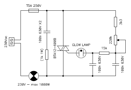
Circuit diagram of the glow-lamp based filament light bulb dimmer.
Because the glow lamp requires a higher trigger (ionization) voltage, about 70 V instead of 30 V, some adjustments to the different resistors and capacitors may be required, but in my circuit the substitution worked straight away, I just dropped a glow lamp in place of diac and that was it.
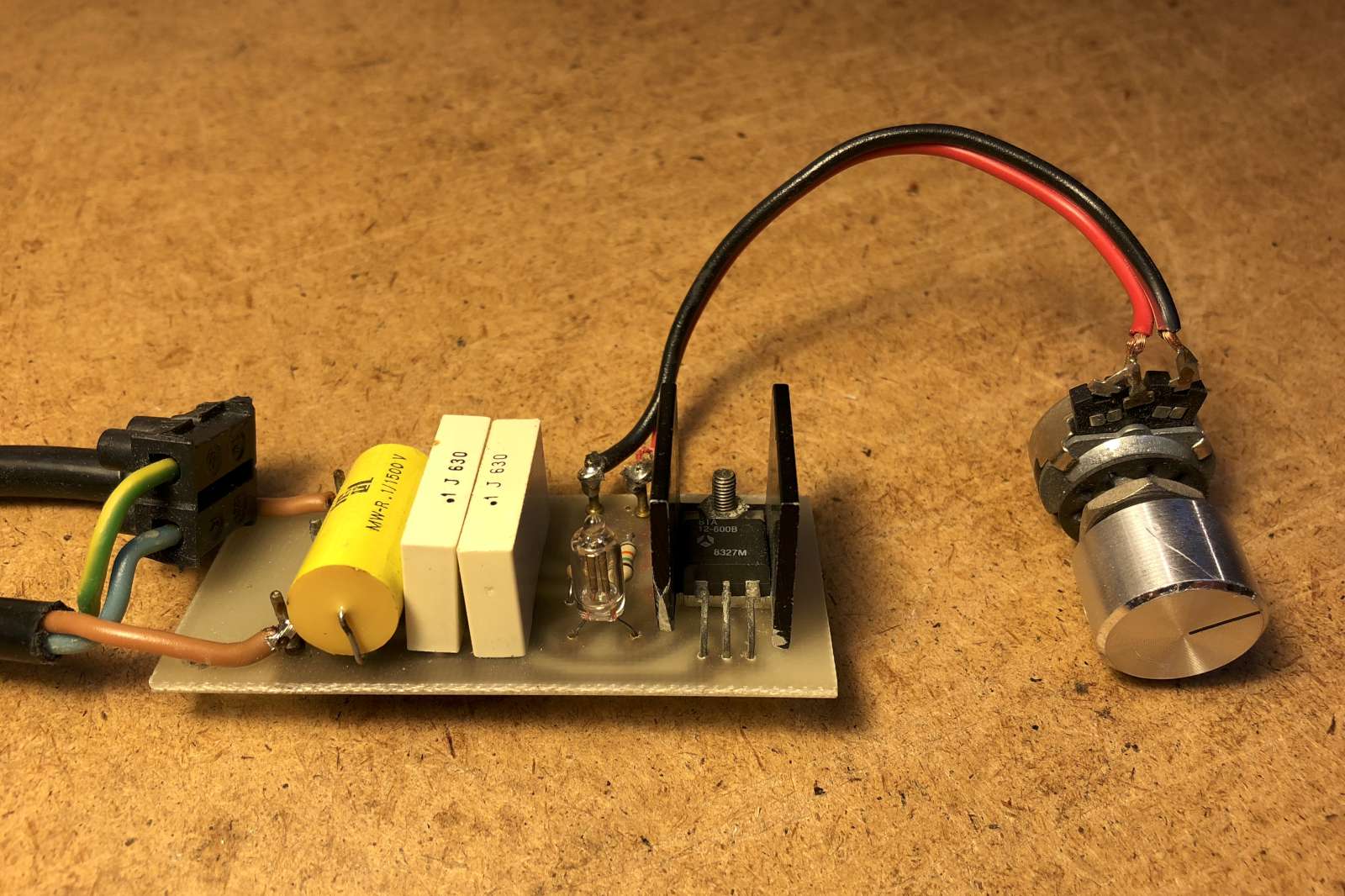
Picture of the dimmer. The glow lamp is clearly visible. (click to enlarge).
Don't expect to see the glow lamp glowing: pulses are very short and current is very low. In complete darkness, I was able to observe a dim orange light, but it was not enough to be captured in a picture... or, should I say, a picture good enough to be presented here.
A xenon tube stroboscope is another classic application that commonly uses a diac to trigger the tube. Here again, a neon glow lamp can successfully replace the diac. The circuit works as follows: the mains voltage is rectified by the 1N4007 diode and charges two parallel 2.2 μF high voltage electrolytic capacitors that are used as energy storage for the xenon lamp. The 1 MΩ resistor in parallel with them acts as bleeder to slowly discharge this energy when the circuit is powered off. A series 1 kΩ resistor with the mains supply plays a double role: it limits the inrush current when the circuit is first switched on and prevents the capacitors from charging too quickly if the frequency of operation is set too high, as this would drive the tube with too much energy and damage it.
A small current flows through the 1 MΩ resistor and the 4.7 MΩ potentiometer, slowly charging the 100 nF capacitor through the trigger transformer. When the voltage reaches the ionization of the glow lamp, the TIC106D thyristor is triggered and suddenly discharges this 100 nF capacitor through the transformer which provides a high voltage pulse to the xenon tube: the xenon tube ionizes and produces a bright flash. Once the tube has used all the energy in the two electrolytic capacitors, it loses its ionization and the cycle repeats. By adjusting the potentiometer, the speed at which the 100 nF capacitor is charged can be varied, and so does the flash frequency.
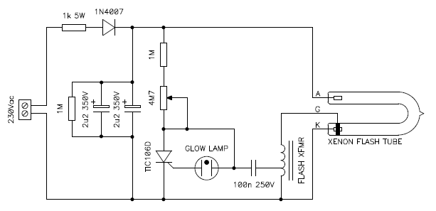
Circuit diagram of the stroboscope.
The energy stored in the electrolytic capacitors can be lethal even when the circuit is switched off or unplugged: even with the bleeder resistor in place, always make sure they are discharged before touching the circuit.
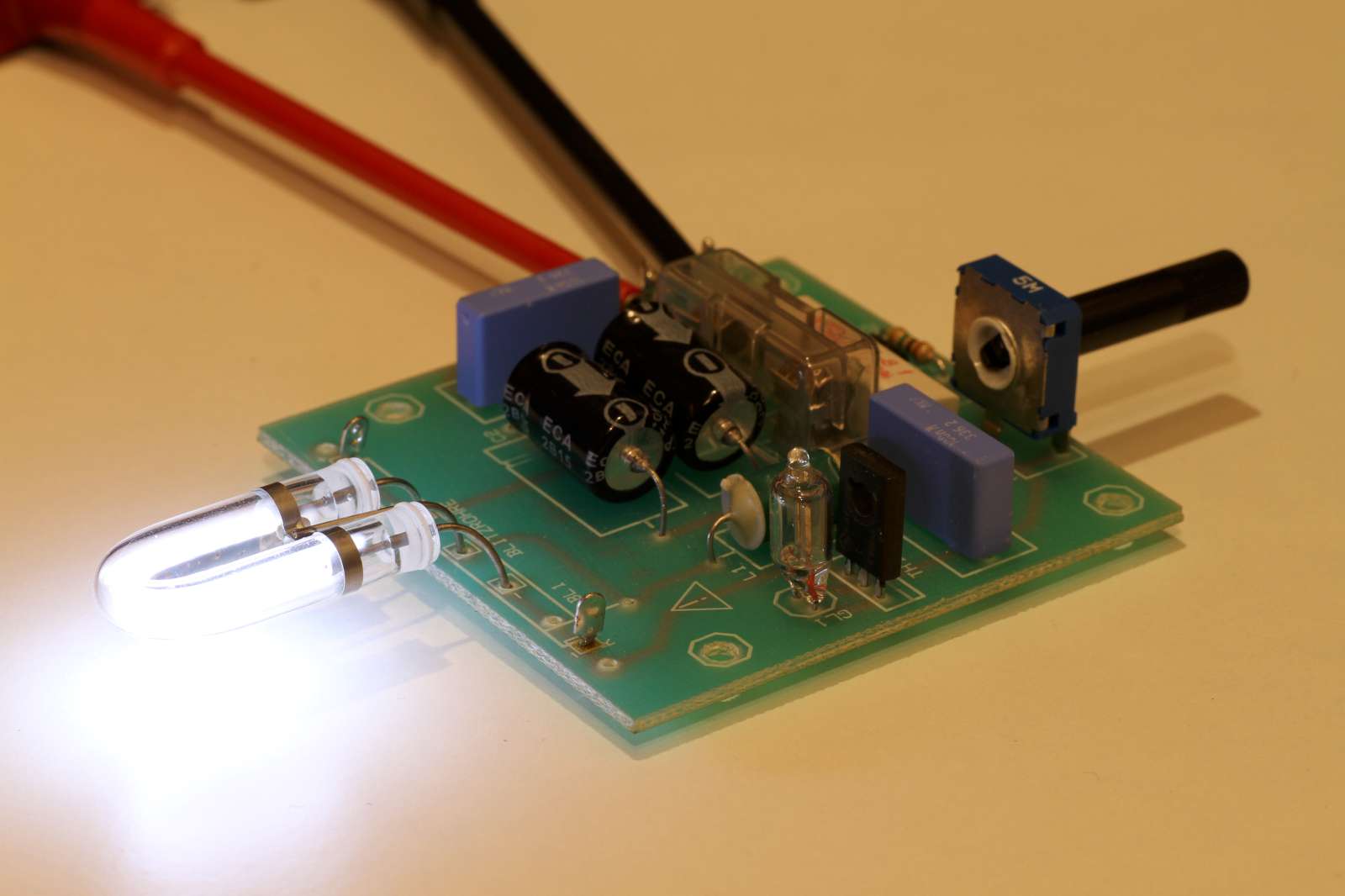
Picture of the stroboscope. (click to enlarge).
As before, the lamp will not visibly glow and the strong flash of the xenon tube will anyway overpower the little light emitted by the glow lamp. Do not expect to see it glowing.
By the way, the xenon flash tube is also a gas discharge tube. But it differs from the glow lamp for its higher gas pressure requiring a much much higher ionization voltage. Here the light is emitted by the gas between the electrodes called positive column and is not a glow covering just the negative electrode. The gas mixture is also different.
Because of their non-linear characteristic and their negative dynamic resistance, neon glow lamps can act as active elements in blinkers and oscillators. This makes very simple circuits, but there are some compromises.
First, the lamp must be driven in its negative resistance region, requiring a high value ballast resistor and a low current. As a result, only the negative electrode glows, only on part of its surface and the glow is not very bright. Then, glow lamps are quite slow: the oscillations will hardly go above 10 kHz or so. The limiting factor is the time it takes to deionize de gas. Finally, exact threshold voltages must be known to predict the exact timing of this kind of oscillators, but tolerances are very large and value drift with time.
You also need at least a supply voltage high enough to ionize the lamp, but a much higher voltage is desirable, as the oscillator is more stable and less sensitive to threshold drifts if supplied with a higher voltage. Just rectifying the mains voltage is usually good enough, even with a 120 V mains.
Even if these are not the most useful circuits today, they are still funny to build and are quite easy to get working. Furthermore, I like the idea of an oscillator with no silicon component nor vacuum tubes.
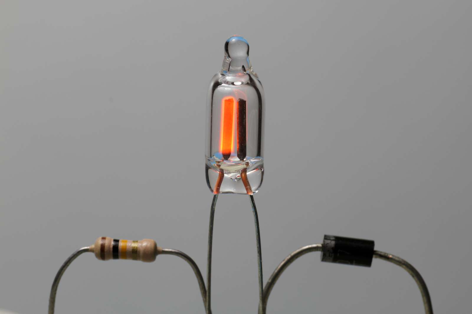
As visible in the diagram below, the mains voltage is rectified by the 1N4007 diode, so that a pulsating DC current flows through the resistor and slowly charges the 470 nF capacitor. If you run this circuit directly with a DC voltage, no diode is needed. If you look at this circuit, it’s just a DC powered indicator light with a large resistor value and a capacitor in parallel with the lamp.
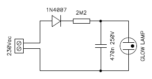
Circuit diagram of the relaxation blinker.
As long as the voltage remains below the ionization voltage, say about 70 V, no current can flow through the lamp. When the voltage reaches the threshold, the gas in the lamp ionizes and the capacitor discharges through the lamp generating a short flash, then the lamps turns off and the cycle starts again.
It's important to use a large value resistor to bias the lamp in its negative resistance region. If its value is too small, the lamp will just switch on and stay on without any oscillation. Changing the capacitor will change the frequency of oscillation: as usual, a larger capacitor will slow down the blinker. The voltage has a large influence on frequency as well: a larger voltage results in a faster blinker.
The following two pictures show the voltage on the lamp at two different power supply voltages: 120 VAC and 230 VAC. From these measurements we can see that the ionization voltage of this particular lamp is 74.8 V and the maintaining voltage is 57.2 V. The frequency changes from 0.57 Hz to 3.3 Hz if the mains changes from 120 VAC to 230 VAC.
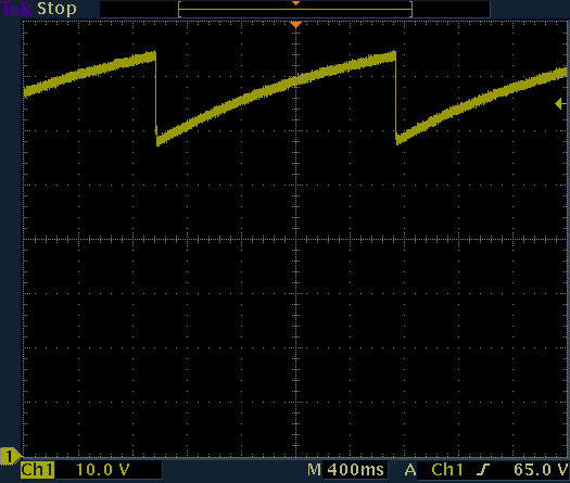
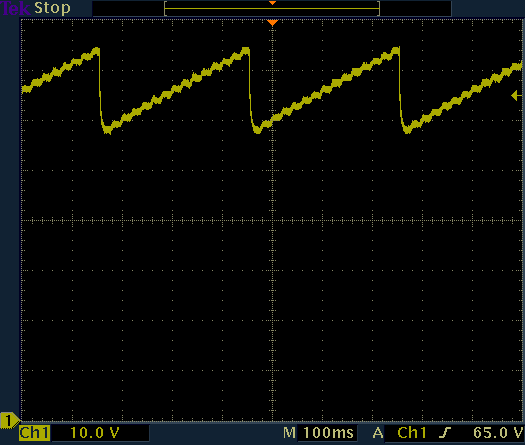
Lamp voltage when powered with a 120 VAC mains (left)
and a 230 VAC one (right).
Note the difference in frequency.
The following equation describes how the frequency can be calculated [1, 2] but it's not worth trying to be too precise because of the uncertainty on the threshold voltages:
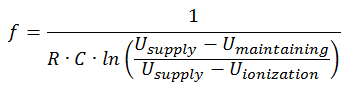
Where ln is the natural logarithm in base e.
Keep in mind that this formula only works if you power the circuit with DC. If you use a rectified pulsating voltage, as done here with the diode and the AC mains voltage, the frequency will be much lower.
As you can see in the picture below, I built this oscillator on a small PCB. The idea was to install it just behind the front panel of a switch box. Unfortunately, I finally installed a steady indicator light instead, because the blinker was not bright enough.
Picture of the relaxation blinker.
Please remark how only the negative electrode of the lamp is glowing.
(click to enlarge).
I also took a short video of this blinker. On the video, the lamp appears to blink irregularly, but this is not the case, it's just because the pulses are very short and interfere with the shutter of the camera. Note, however, that only the negative electrode is glowing and only partially.
Watch the video: blinker-video.mp4
(217,194 bytes, 0:03, H264, 960 × 544, 23 fps).
Even if all glow lamps are similar, their electrical characteristics may be quite different from one lamp to another, so this circuit may require some modifications in order to get it to work with the lamps you have and your mains voltage. Here is a quick summary of what to do if it doesn't work:
| The lamp stays on without blinking: | The resistor is too low: use a larger one. |
| The lamp is too dim: | The resistor is too high: use a smaller one, but not too small otherwise the lamp will stop blinking and stay on. |
| The lamp doesn’t turn on: | The ionization voltage of the lamp is too high or your mains voltage is too low: try a different lamp or a higher supply voltage. |
| The blinker is too fast (or slow): | Use a larger (or smaller) value capacitor. |
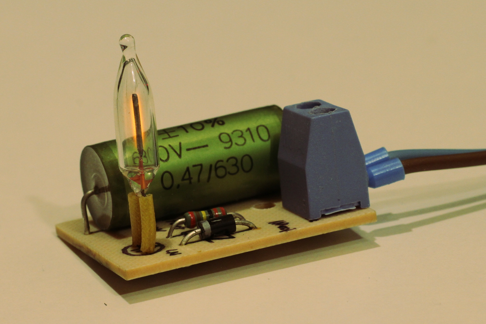
With two glow lamps it's possible to build a simple multivibrator and have them glow alternatively. For this circuit, a true DC voltage is required and is supplied by the 1N4007 diode and the high voltage 16 μF electrolytic capacitor. If needed, this capacitor can be salvaged from an old compact fluorescent lamp. Its value is not critical: aim for several μF or more. The 330 kΩ resistor and the 2.2 MΩ trimmer control the frequency of the oscillations by varying the DC voltage. For fixed frequency operation, both can be replaced with a single 1 MΩ 0.25 W resistor.
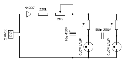
Circuit diagram of the twin lamp multivibrator.
When the circuit is powered on, the diode will rectify the AC mains voltage and slowly charge the electrolytic capacitor through the resistor and the trimmer. When the voltage becomes high enough, one of the two lamps will ionize and turn on. Because of parameter variations, one of the two lamps will always strike first. As soon as this happens, the voltage on its electrode drops from its striking voltage to its burning voltage which is 10 to 20 V lower. Because of the 150 nF capacitor, this 10 to 20 V drop also appears on the other lamp, lowering its voltage by the same amount.
Now, suppose that the first lamp is glowing. The voltage across it is its burning voltage, say 50 V. The 150 nF capacitor now charges through the 1 MΩ resistor of the other lamp. The voltage on the second lamp rises and when its ionization voltage is reached, say 70 V, the second lamp switches on. Now the voltage on the second lamp suddenly drops from 70 to 50 V, its burning voltage. Again, because of the 150 nF capacitor, this 20 V drop appears also on the first lamp that turns off, because the voltage is now below its maintaining voltage. Now the roles are reversed, the 150 nF charges in the other direction and the cycle repeats.
This is quite a critical circuit and requires two almost electrically identical glow lamps. Not every lamp will work here: if it doesn't work, try a different set of lamps or a higher supply voltage.
The voltage on the two lamps can be observed in the following graph, the frequency is about 1.4 Hz. Here the circuit was powered with a 230 VAC mains. Unfortunately, in my case, the two lamps are too different to run at a lower voltage and it stop oscillating below about 150 VAC. You can see the differences in ionization and burning voltages as a shift between the yellow and blue trace. But it's possible to run this circuit with a 120 VAC mains if the lamps are better matched.
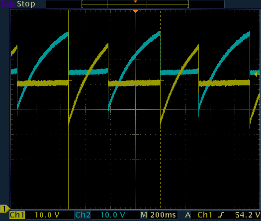
Voltage on the two lamps.
As you can see, the voltages on the lamps are not square waves, but the current in the lamps are. If you need to generate a square wave, you can put a resistor (10 kΩ or so) in series with each lamp and get the output across it.
Please also remark that it takes some time for the electrolytic capacitor to charge when the circuit is switched on, so don't expect it to start immediately. Conversely, once switched off, it will continue blinking for several seconds.
Keep also in mind that the charge in the high voltage electrolytic capacitor can be lethal even when the blinker is switched off: always make sure it's discharged before touching any part of the circuit!!! Adding a bleeder resistor across it would be a good idea, but because of the high value charging resistor, the bleeder should be much larger, say 10 MΩ or so: it will take a very long time to discharge the capacitor through the bleeder. So, always use extreme care and build it only if you know what you're doing and at your own risk.
The multivibrator I built is visible in the picture below. I opted for a small etched PCB, but this is not strictly necessary.
Pictures of the twin blinker. (click to enlarge).
I also took a short video of the operation of this blinker. As usual, the lamps are in their negative resistance region and don't glow very brightly. And of course, since they are operated in DC, only the negative electrode glows.
Watch the video: twin-blinker-video.mp4
(254,545 bytes, 0:03, H264, 960 × 544, 23 fps).
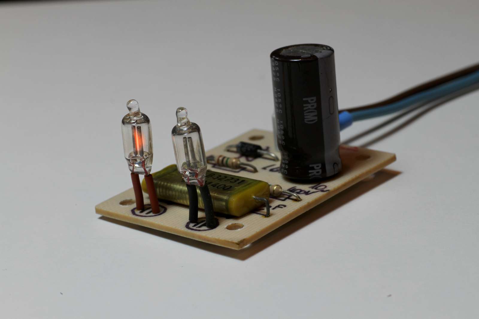
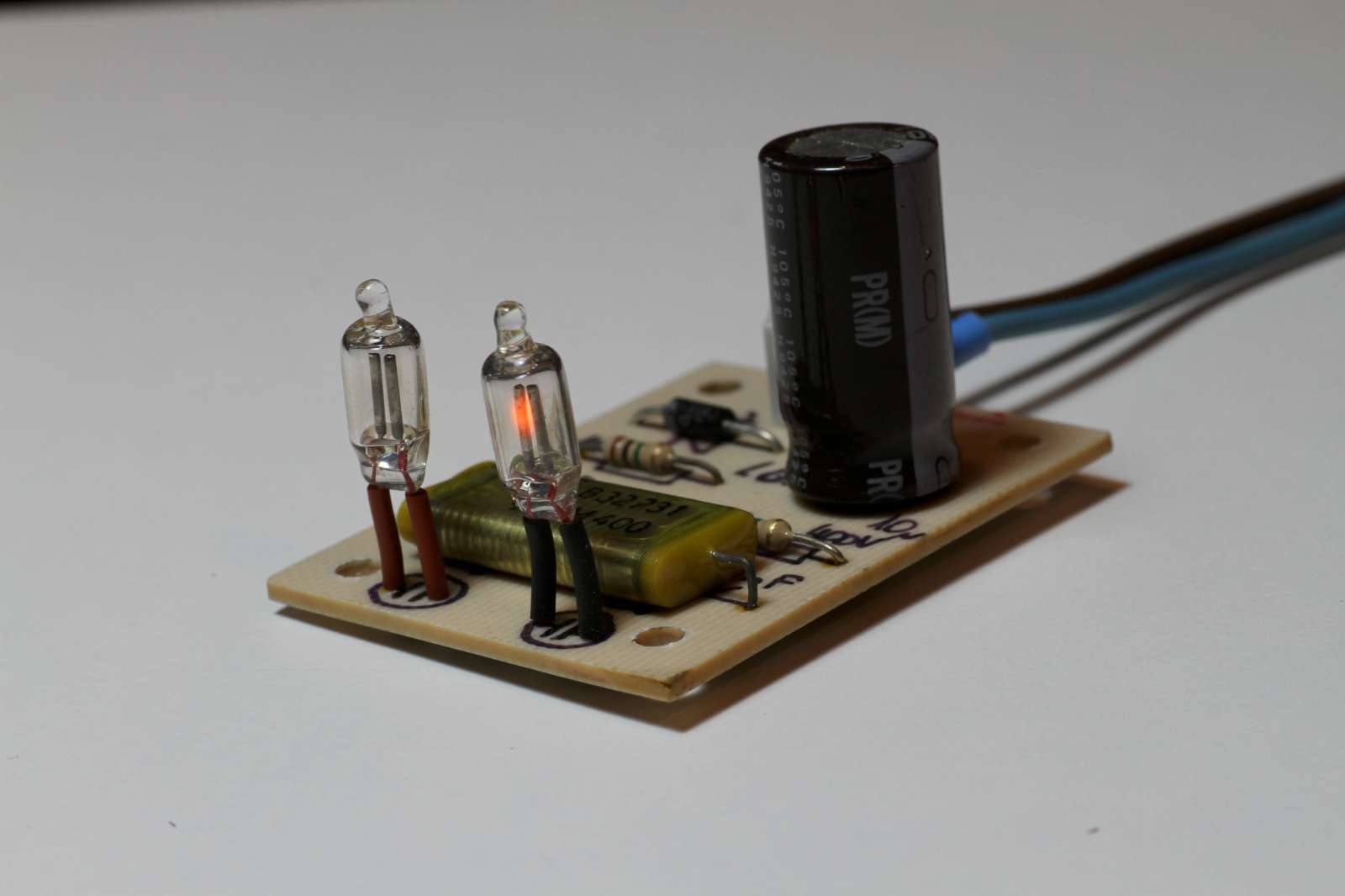
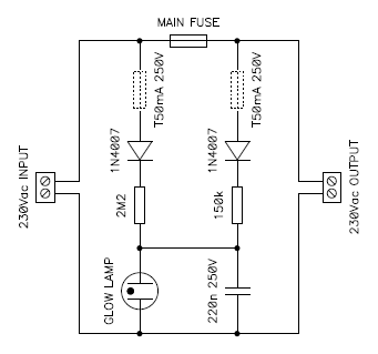
Neon glow lamps are widely used as fuse monitors. The simplest and more effective way of doing so is to connect the lamp in parallel with the load as a mains voltage indicator light, so that when the lamp is on, you know that the fuse is good. An alternative way is to connect the lamp in parallel with the fuse as a switch orientation light, so that if the fuse is good the lamp is off and it switches on when the fuse blows; as long as there is a suitable load connected, of course. The same constraints as for the orientation light apply here.
When I connect something in parallel with a fuse, like the glow lamp here, I usually add an additional fuse to make sure that in case of failure, the main fuse is never bypassed. This additional fuse is optional, but it's a good idea; in the circuit diagram it's drawn with dotted lines. The minimum current rating for small fuses is usually 50 mA and this is the value I normally use. The current in the glow lamp is, of course, much less.
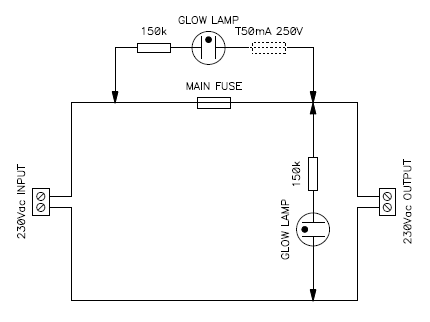
Circuit diagram of glow lamps as fuse monitors.
Both options are possible also at the same time.
Another idea for building a fuse monitor is to use a relaxation oscillator. Here, the neon glow lamp indicates by remaining lit that the fuse is good, by blinking that the fuse has blown and by remaining off that there is no power.
The circuit, visible in the figure below, is based on the relaxation oscillator (blinker) described before. When the fuse is good, the lamp is mainly powered via the 150 kΩ and its series diode. The 2.2 MΩ resistor and its series diode have negligible effect. This biases the lamp in its positive dynamic resistance region that stays on without blinking. If the fuse is blown, only the 2.2 MΩ resistor powers the lamp that is now biased in its negative dynamic resistance region and blinks. The capacitor sets the frequency of oscillations. Of course, if there is no power, the lamp stays off.
Circuit diagram of the blinking fuse monitor .
As before, the two additional fuses drawn with dotted lines are optional and are just to make sure that the main fuse is never bypassed should this little circuit fail.
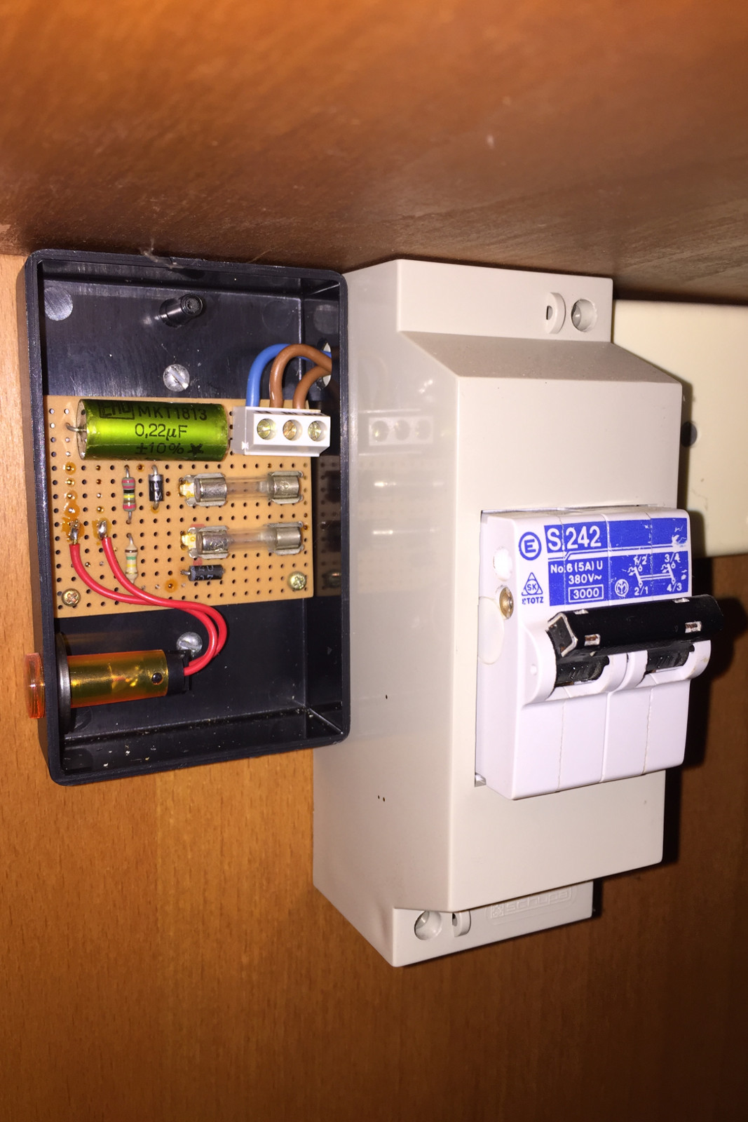
Picture of the blinking fuse monitor. (click to enlarge).
I built this monitor in a small plastic box that I installed next to a circuit breaker that represents the main fuse here. The two extra fuses are clearly visible. This circuit is funny but I have to admit that the lamp isn't very bright. After about a decade of continuous service the lamp ended up completely black and I had to replace it with a new one.
Nixies are a special type of neon glow lamps used a display tubes. Instead of just one, they have several cathodes (negative electrodes) shaped with the forms to display. For example, most nixie tubes have ten cathodes shaped like the digits from 0 to 9. All cathodes are left floating except the one we want to show, which is connected to the circuit. As the current flows, the surface of that cathode will glow and its shape will be clearly visible, while all other cathodes will stay dark.
The anode is usually in the form of a grid on the front and back side of the tube, thin enough to let most of the light through. In the picture, its honeycomb structure is clearly visible.
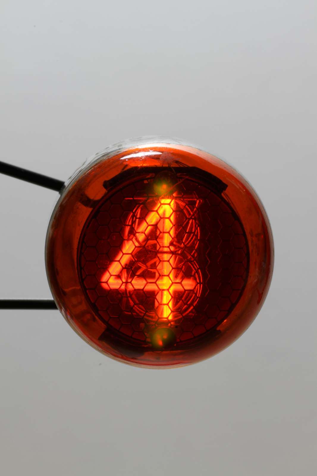
Picture of a Philips Z520M nixie tube with the "4" shaped
cathode connected to the circuit. (click to enlarge).
Nixie tubes require a DC voltage in the 150 to 300 V range, depending on the model. As all neon glow lamps, they also need a ballast resistor, usually in the 10 to 100 kΩ range, to limit the current to 1 to 2 mA connected to the anode terminal. The digits are switched on and off by connecting the corresponding cathodes to ground, usually with a high voltage transistor. The ground potential is the same for the nixie high voltage supply and the digital driving circuit.
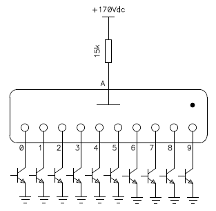
Basic connection of a nixie tube.
With the exception of some tubes equipped with one or two decimal points, only one cathode can be connected at once. Connecting more than one simultaneously may be disappointing, as only one may glow or maybe only partially, but this won't damage the tube. Decimal points, on the other hand, are designed to operate in conjunction with a main cathode and behave as expected if connected at the same time.
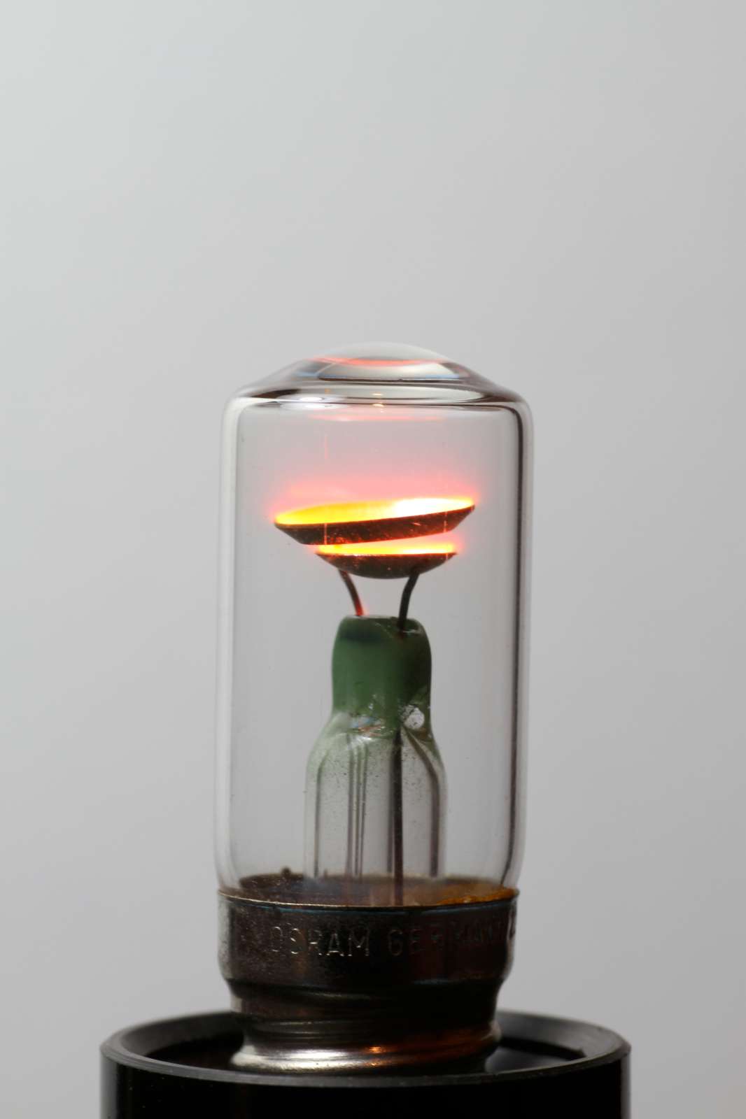
When a glow lamp is ionized, the voltage across its terminal is fairly constant. Large variations in the lamp current only have a small effect on the voltage. So, glow lamps, can be used as voltage regulators, behaving almost like big Zener diodes.
Now, common glow lamps are built to work as lamps, so their voltage regulation is not very good. They aren't adjusted to any particular value and they aren't stable over time. But, voltage regulator tubes exist: they are explicitly built for this purpose and are based on the same glow discharge as common neon glow lamps. They can be built with tight tolerances and good temperature coefficients. They have large electrodes to carry higher currents, the electrodes are not coated for better long term stability and they are carefully aged by the manufacturer before use.
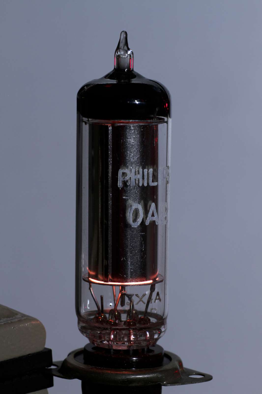
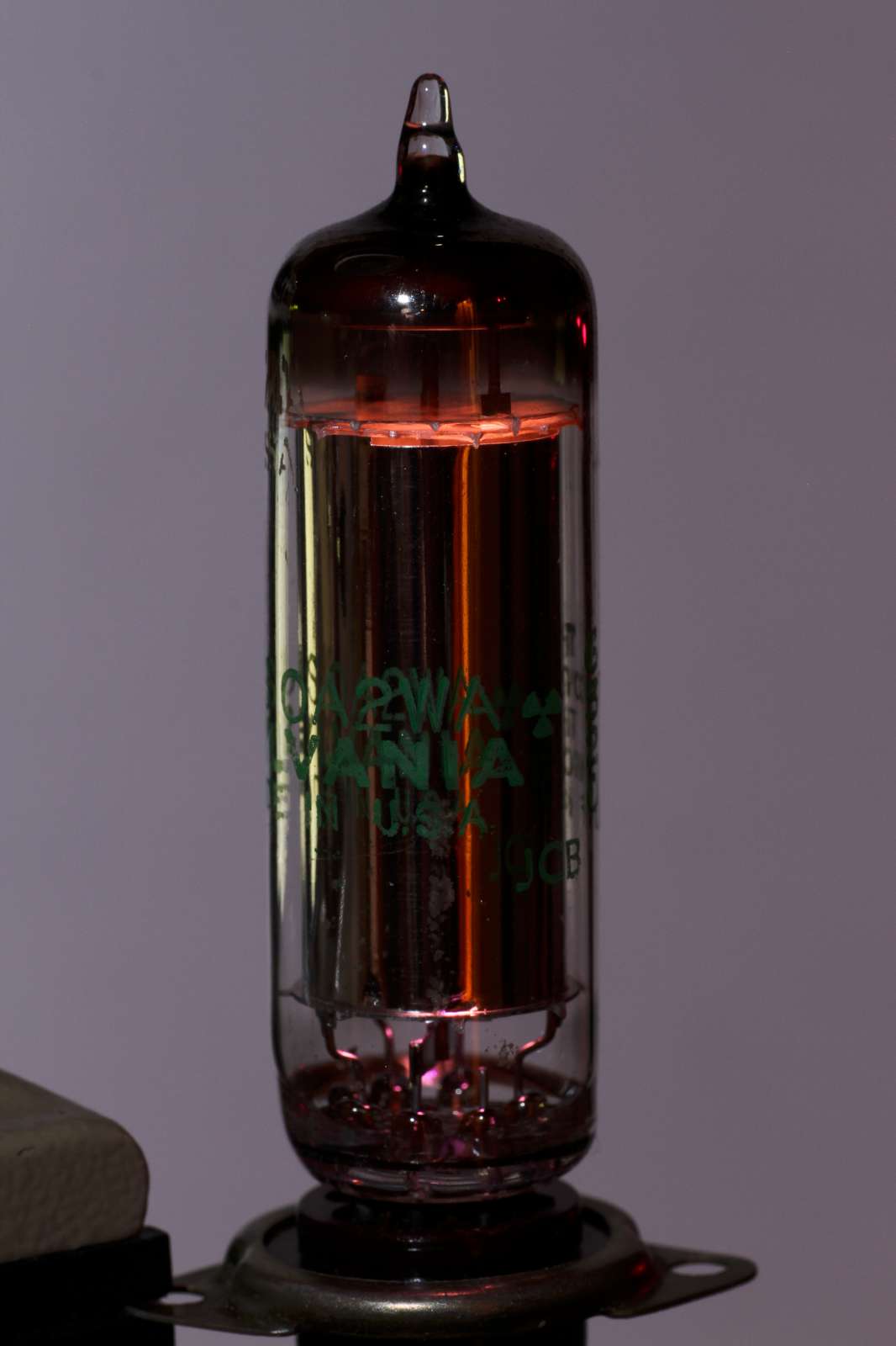
Picture of two 0A2 voltage stabilizer tubes rated for 150 V.
On the left a tube manufactured by Philips and on the right a tube
manufactured by Sylvania.
Both tubes are on, but only little light leaks out.
(click to enlarge).
These tubes are quite large, the size of a vacuum tube. The glow inside is not always clearly visible: some are quite open and shine brightly, others make quite difficult to tell if the tube is actually on or not. Most of them are polarized: they have an anode and a cathode that should not be reversed. There are models rated typically from 75 to 150 V and have working currents in the 5 to 40 mA range. [3]
They are used like Zener diodes, usually in parallel with the load and connected to the unregulated supply with a limiting resistor. The example below uses a 0A2 tube, which is rated for 150 V. The 22 kΩ resistor limits the current to about 9 mA for this application. This particular tube is rated 5 to 30 mA.
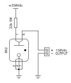
Typical circuit diagram of a 0A2 tube based voltage regulator.
Most of these tubes have internal connections that can be used to disconnect the load if the tube is removed from its sockets. If not, should this happen, the full unregulated voltage will appear on the load.
In spite of Zener diodes that only have one threshold voltage, glow regulators overshoot at startup: when the voltage is first applied, it will rise all the way up to the ionization voltage, the tube ionizes and the voltage drops to the normal operating voltage which is a bit lower. Depending on the application, this may or may not be a problem.
Furthermore, the unregulated voltage must be high enough to allow the tube to ionize; for example, the 0A2 requires a minimum of 180 V in normal lighting conditions and, because of the dark effect, 225 V in complete darkness. Some tubes contain traces of radioactive materials to minimize the dark effect; but this is not the case of the 0A2.
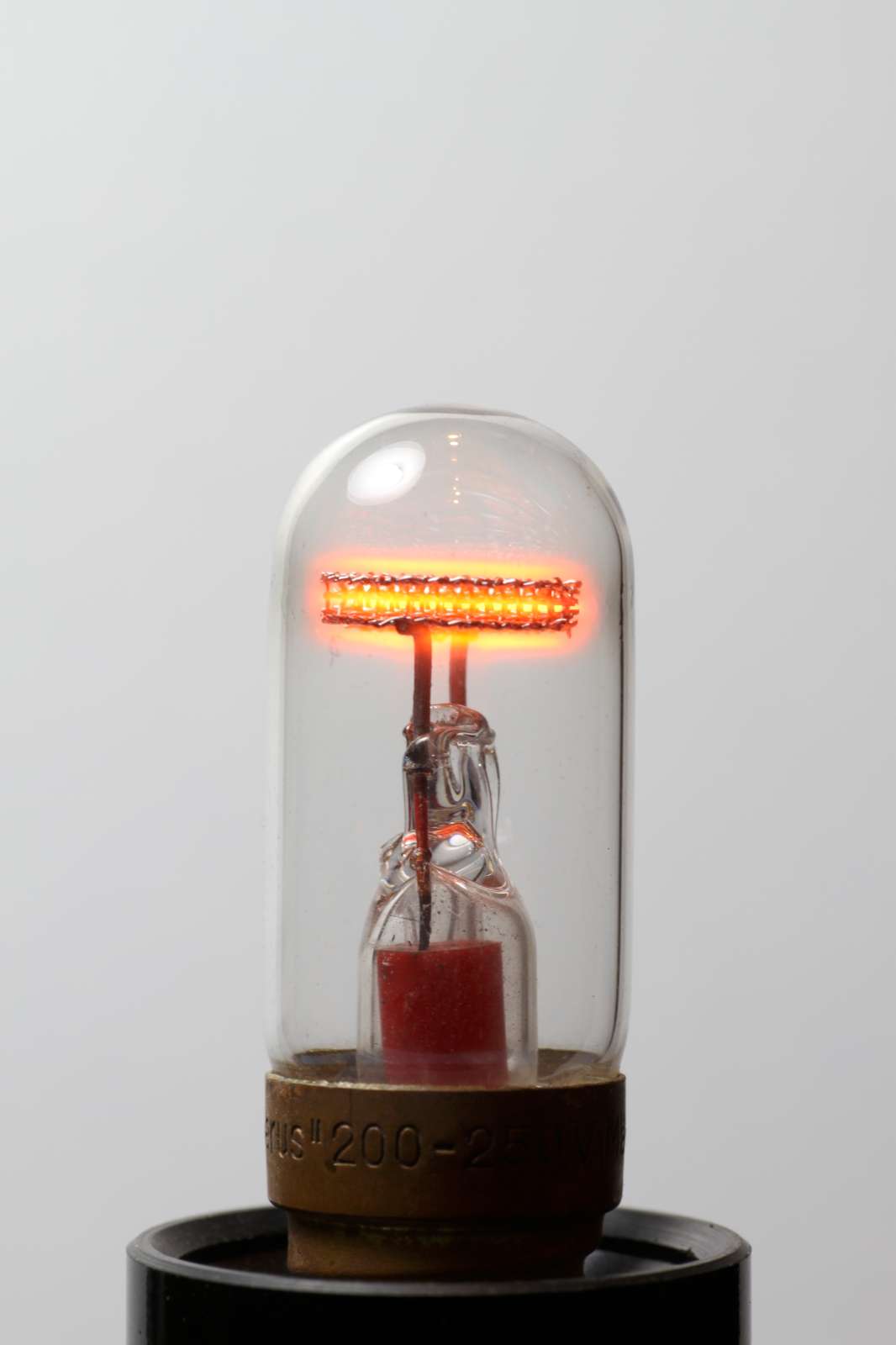
Because of their unique glow that covers the negative electrode, neon glow lamps have been used for decoration, with electrodes of all sorts of size and shape. The goal here is not to show a gallery of bizarre lamps, but to show a few of them that are technically interesting.
Flame simulating lamps are curious devices: the electrodes have the shape of a flame and are about 1 mm apart. The discharge doesn't cover the whole surface and moves around. Actually, all gas discharges have a tendency to flicker, because they depend on gas pressure and temperature. The gas cannot be in equilibrium because of the discharge that heats the gas and moves its atoms around. Normally, a stable discharge is desired and measures are taken to stabilize it, but here, it's the opposite: the lamp is built to flicker.
Normal glow lamps have small electrodes that are designed to glow on their full surface as steady as possible. Still, every now and then, you'll find a lamp where the glow is only partially covering the electrodes and sometimes moves around. This happens with brand new lamps, but is more common after many hours of service. To enhance the flickering effect, the electrodes are built to offer a large surface, much larger than a regular glow lamp, so that the lamp is operated in its normal glow region, where the discharge doesn't cover the whole surface.
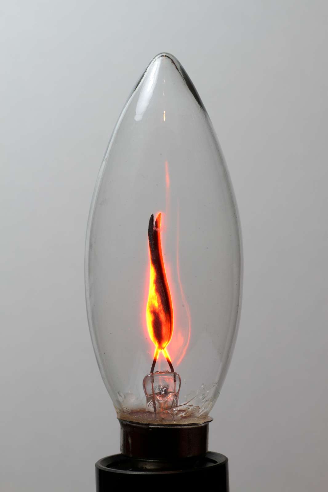
Picture of a flame simulating lamp. (click to enlarge).
The electrodes are flat and placed almost parallel and close to each other. The distance is in the 0.5 to 2 mm range and the flickering glow has a tendency to start where the electrodes are closer and to move away towards the electrodes are farther apart. During design and manufacturing, the gas composition and pressure, electrode spacing, and ballast resistor are carfully chosen for optimizing the flickering effect [6].
The electrodes have a black appearance, because they are coated with barium azide, a salt commonly used in vacuum tubes getters. During manufacturing, when the lamp is evacuated the electrodes are heated to convert the barium azide into barium, with liberation of nitrogen gas. For the flickering effect, it's important that this process is not carried all they way, but some "trace amounts" of nitrogen are left the electrodes [6]. This being said, I've seen lamps with uncoated electrodes flickering: the procedure described in [6] certainly helps, but it's not necessary.
The way the glow moves around is roughly cyclical following a sort of pattern, but with some randomness in it. It stays more in some spots than others but moves randomly, sometimes quicker, sometimes remaining in the same spot for half a second or more. The flowing video clearly illustrates this effect.

Watch the video: flame-simulating-lamp-video.mp4
(1,085,115 bytes, 0:04, H264, 960 × 544, 23 fps).
The ionization voltage of the lamp I have is about 150 V in both directions. The current is around 8 mARMS when powered with 230 VAC, but the current "dances" slightly following the flickering effect.
Current as a function of voltage for this flame simulating lamp.
Voltage is on the horizontal axis, current on the vertical one.
The curve is not exactly repetitive and dances slightly on the screen
following the flickering effect.
As in regular neon glow lamps, only the negative electrode glows and they both appear to glow because of the AC power supply. But the alternating current has nothing to do with the flickering effect: the lamp glows with the same flame effect even if powered with a nice and smooth DC voltage, but only on the negative electrode.
Current consumption of a flame simulating lamp powered with smooth DC
voltage.
The variations in current follow the flickering effect.
Finally, let's have a look at the light spectrum emitted by this lamp. We see that the majority of the spectral lines are from neon that emits precisely at 585, 610, 640, 703, 725, 744, 838 and 878 nm. There is also some helium with its peaks at 588 and 668 nm. On the other hand, I don't see any nitrogen: it would emit at 747, 822 and 868 nm. The fact that we don't see it glowing doesn't mean that there is no nitrogen in the lamp, but we cannot confirm that it's there.
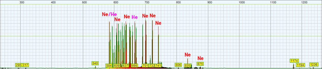
Spectrum of the light emitted by this flame simulating glow lamp.
The wavelength in nm is on the horizontal axis and the amplitude in arbitrary
units is on the vertical one.
There are all sort of decorative lamps with electrode made in all sorts of shapes. I choose this one because its structure is interesting. It has two main electrodes that form together the shape of a rose, each being the half of the final flower, one is the back petals and the other the front ones. When the lamp is AC powered, both electrodes glow and the complete rose glows with a pinkish-rose color.
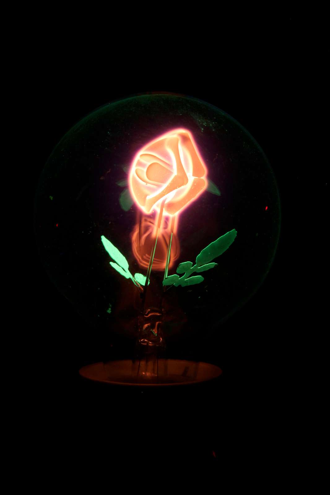
Picture of a rose decorative lamp when AC powered.
In this picture the color of the petals is not well represented, they are
pinker in reality. (click to enlarge).
But there are two other parts that have the form of two leaves, each one connected to a main electrode. When the lamp glows pink, the leaves glow green. The leaves are coated with a green fluorescent varnish. Here, it's not the gas that is glowing in the immediate vicinity of the electrodes as on the petals, it's the varnish that glows.
The interesting part is why the leaves are glowing. Are the leaves two electrodes struck by electrons or ions, or are they just two electrically inert elements excited by uncharged particles such as UV light? Well, there is an easy way to find out: DC powering the lamp.
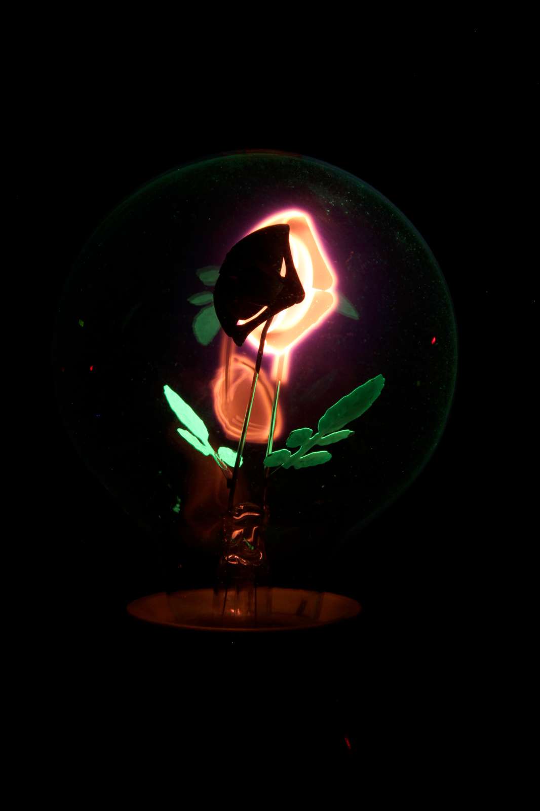
Picture of a rose decorative lamp when DC powered.
Please remark that only one electrode glows pink, but both leaves glow green.
(click to enlarge).
When DC powered, as expected, only half of the flower glows pink while the positive electrode stays dark. But both leaves are still glowing as before. This means that what is exciting the green fluorescent varnish are not electrons nor ions. If this was the case, their electrical charge would steer them to only one leaf. The fact that each leaf is connected to one electrode is just for mechanical support reasons but the leaves are not electrodes and don't take part to the current flow.
One possible explanation on what causes the leaves to glow is UV radiation that is unaffected by the polarity of the electrical field. To verify this theory, I measured the spectrum of the light emitted by this lamp. But from the spectrum, I could only tell that it contains mainly neon (that emits at 585, 614, 640, 703, 749 and 878 nm), some helium (emits at 588, 668 and 707 nm) and some argon (emits at 810 nm). I don't see any nitrogen and any mercury that could emit UV light, and I don't see any UV light, either. So, I don't know why the leaves glow;, but for sure it's not charges (electrons, ions) that hit them nor UV radiation.

Spectrum of the light emitted by this flower-shaped glow lamp.
The wavelength in nm is on the horizontal axis and the amplitude in arbitrary
units is on the vertical one.
A radio frequency (RF) field can directly ionize the gas inside a neon glow lamp, if it's strong enough. Radio frequency electromagnetic waves are non-ionizing radiation, but neon glow lamps are designed to be ionized by an electric field, so there is nothing surprising in the fact that a non-ionizing radiation can ionize a neon glow lamp. In this case, there is no need to connect the electrodes to any circuit; the electromagnetic field will couple with them directly and they act as antennas. Actually, a low pressure gas will ionize and glow in a strong RF field even if no electrodes are present at all, but the extra coupling to the electrodes helps.
As one can see in the following picture, a mini Tesla coil is enough to excite the neon glow lamp: even if I'm holding the lamp by the glass which is a good insulator, it still glows in my hand. Touching the electrodes with my hands increases the intensity. Here, the power generated by the mini Tesla coil is quite small and harmless, but as a general rule, one should avoid exposing himself to strong electromagnetic fields. The frequency her is around 3.3 MHz but I don't know intensity of the electromagnetic field.
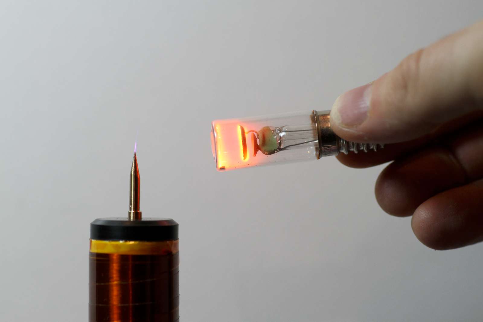
Picture of a neon glow lamp in a strong electromagnetic field.
Please remark that the lamp is not connected and that it glows even when I'm
holding it by the glass. (click to enlarge).
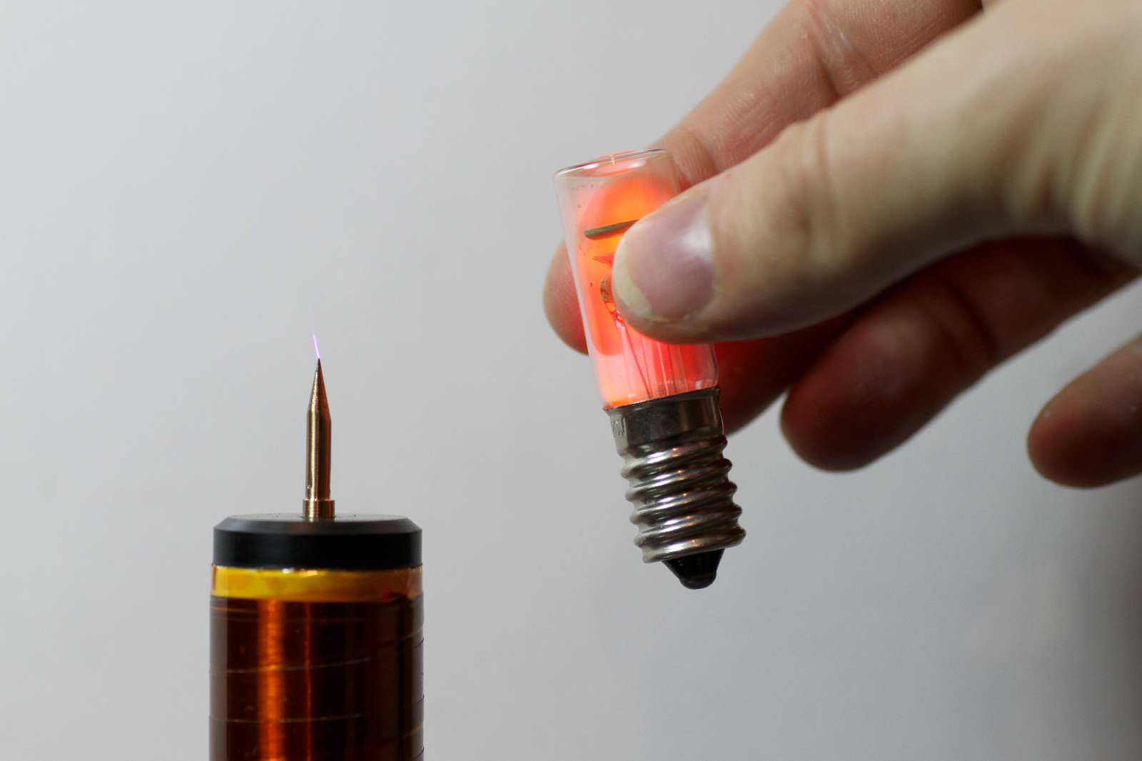
In the following picture you can see a neon glow lamp held with plastic tweezers: no electrical connection is present, but the lamp glows, excited by the electromagnetic field.
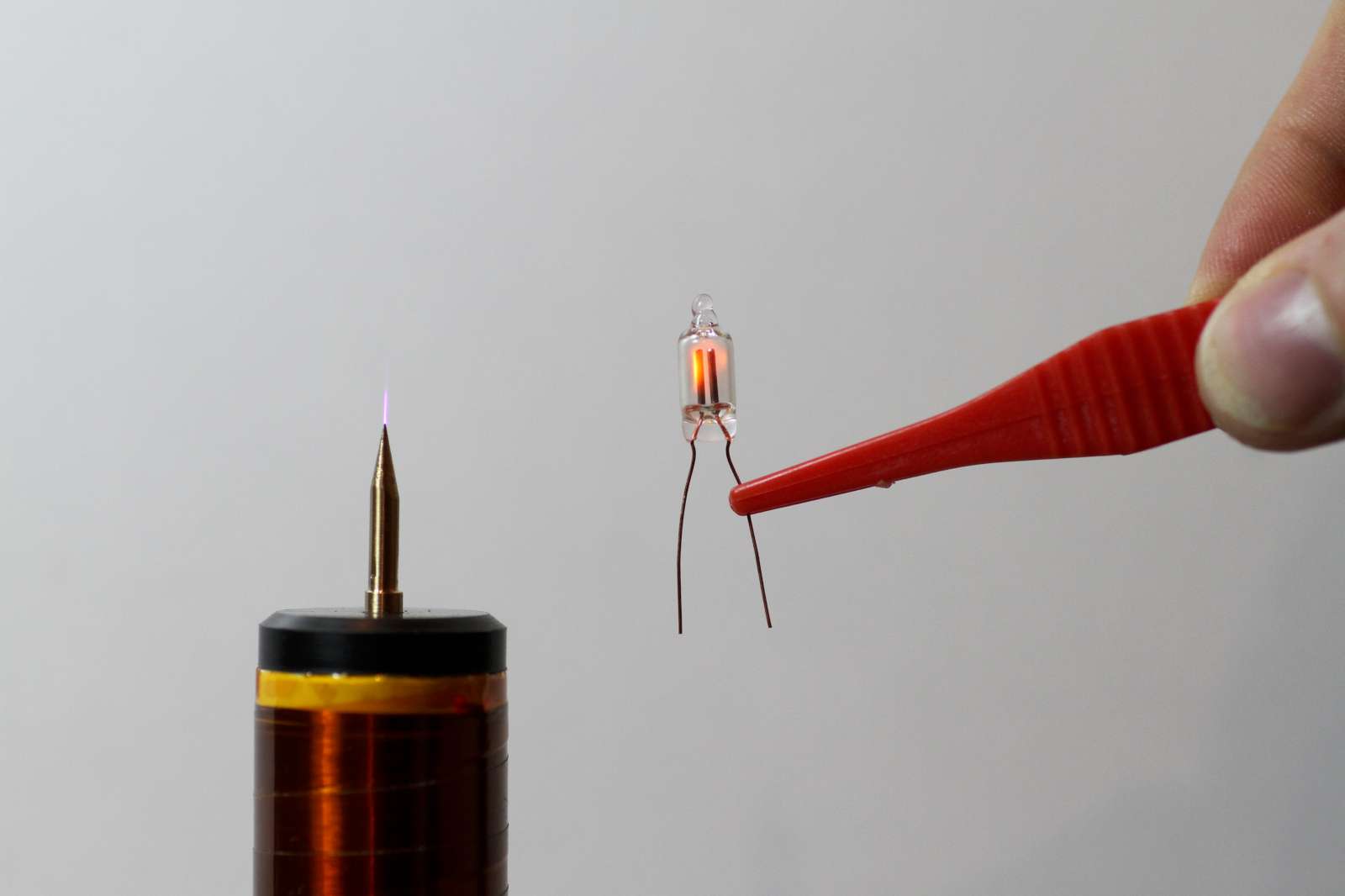
Picture of a neon glow lamp in a strong electromagnetic field.
Please remark that the lamp held with insulating tweezers.
(click to enlarge).
In order to ionize the gas in a glow lamp, you need a strong electromagnetic field. For example, the one generated by your mobile phone which has a power of about 1 W, even very close to the antenna, won't be enough. You need more power.
In the picture below, I'm holding a 120 cm fluorescent tube. Ok, technically it's not a neon glow lamp, but it's a low pressure gas discharge tube that also ionizes in presence of strong electromagnetic fields. The structure in the background is an insulated tower that I used as antenna for testing a 137 kHz transmitter. When the transmitter is operating, the field is strong enough to ionize the tube. Again, one should avoid exposing himself to strong electromagnetic fields, so don't repeat this experience.

A fluorescent tube in a strong RF field also glows.
Here, at the base of an insulated tower used as 137 kHz transmitting
antenna. (click to enlarge).
If the lamp is completely insulated and not mounted in a circuit, it requires a strong electromagnetic field to ionize. Not only the field has to be strong enough to ionize the gas, but it also has to provide the power for the lamp to glow.
But if the lamp is biased with some voltage lower than the ionization voltage, a weaker electromagnetic field can ionize the lamp. If the voltage is higher than the maintaining voltage, once the RF field ionizes the lamp, the lamp stays on until le voltage is brought below this threshold. It's therefore possible to build a simple and reasonably sensitive RF field monitor with a neon glow lamp.
Suppose that you have a safe (current limited) voltage source of about 90 V or more, for example as described below. If you manually adjust the voltage to a point that is just below the ionizing value of your lamp, a small RF field is enough to ionize the lamp.
The circuit diagram is presented below. A potentiometer adjusts the voltage on the lamp. A pushbutton (or a switch) allows quickly switching the lamp off and on again to deionize it when needed. A decoupling capacitor and two inductors keep the RF separated from the power supply. An optional dipole antenna can be connected in parallel with the lamp to further increase its sensitivity.
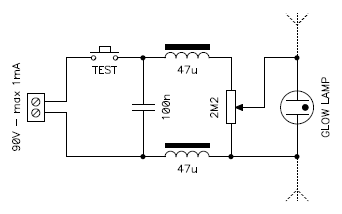
Circuit diagram of the RF field monitor.
Both AC and DC will work for this application; if you use DC, the lamp will keep glowing after being ionized by the RF and you'll have to manually rearm the detector with the "test" switch; if you use AC this won't be necessary as the lamp extinguish at every half cycle.
To use this monitor, start with the 2.2 MΩ potentiometer in its 0 V (bottom) position, power the circuit on when no field is present and slowly raise the voltage until the glow lamp strikes. Now turn the potentiometer in the other direction just slightly and verify by cycling the power that the lamp stays off and you're ready to go: an RF field will make the lamp glow.
For testing you can try a cellphone or a handheld transmitter: the bulb will glow in proximity of the antenna. Keep in mind that some Watts of RF power are required. Connecting a small dipole to the lamps terminal dramatically increases its sensitivity, especially if it's cut to be resonant at the desired frequency.
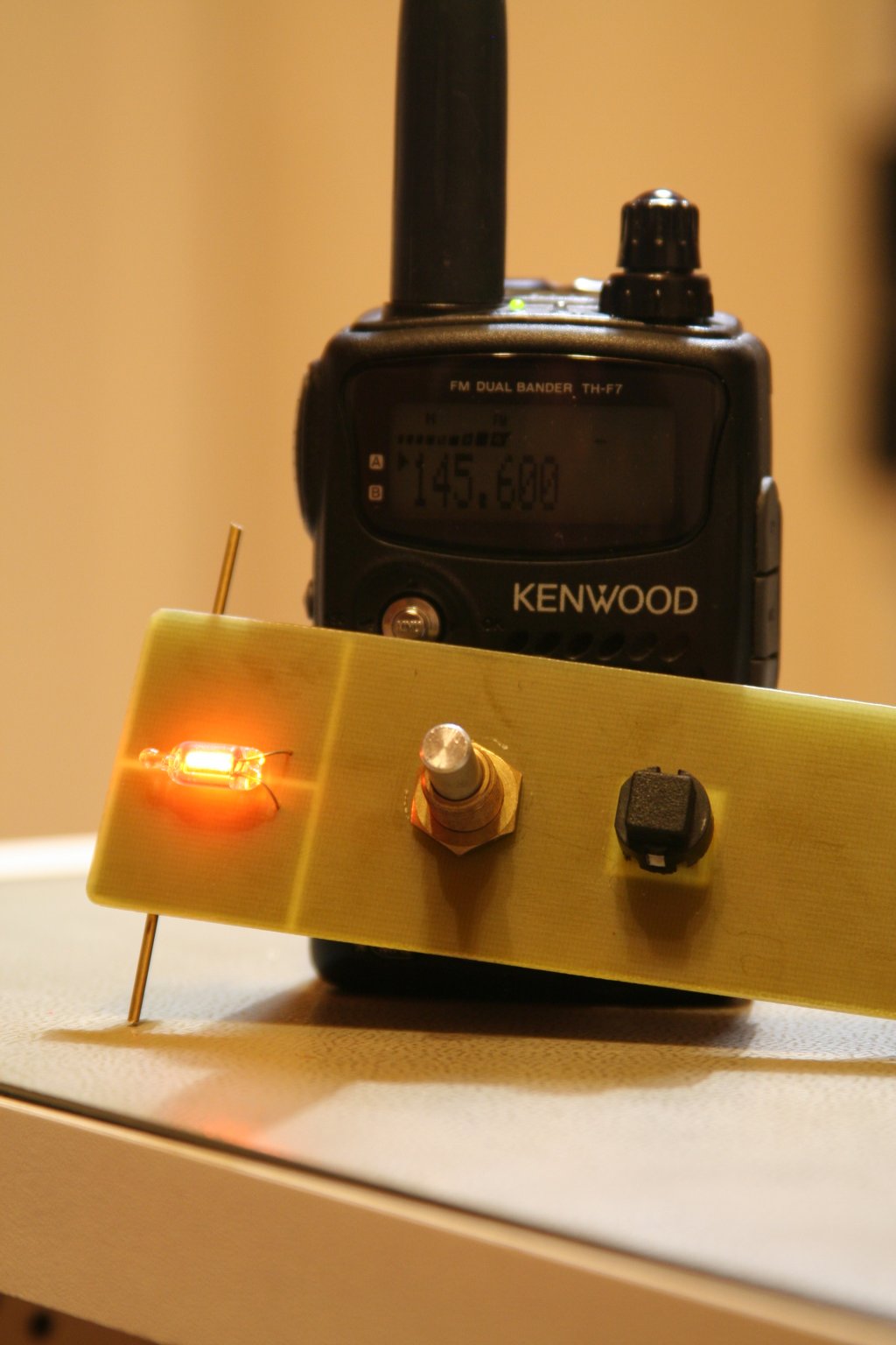
Picture of the RF field monitor in front of a handheld transceiver.
For this picture, I short-circuited the pushbutton.
Since this monitor is DC powered, the lamp keeps glowing after the
transceiver is returned to receive mode. (click to enlarge).
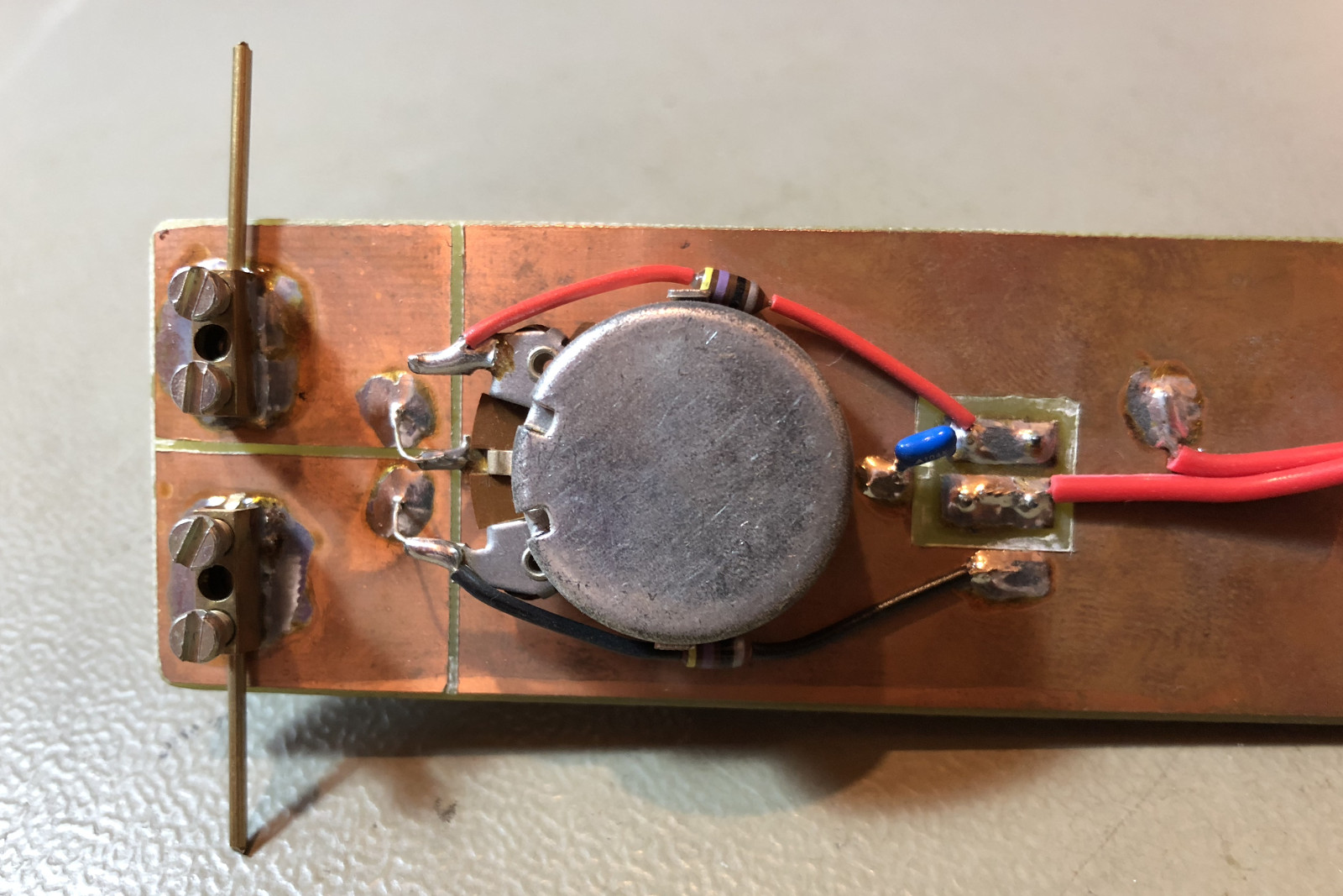
Picture of the back side of the RF monitor.
Because nothing is insulated in this prototype, it's important to use a safe
high voltage source. (click to enlarge).
To power this RF monitor and glow lamps in general, a safe high voltage generator can be very useful, as the mains voltage is dangerous. I stumbled across a Lienar Technology application note [4] describing a high voltage power supply for a pulse generator. This simple circuit works very well with glow lamps as it provides 90 V with maximum 1 mA starting from a single 1.5 V AA battery. There is no danger in touching the high voltage output as long as it's not used to charge a large capacitor.
It's based on a micro-power DC/DC converter type LT1073 and a diode voltage tripler. Here, you need a LT1073: a LT1073-5 or LT1073-12 won't work. The 150 μH inductor is the most critical part of this circuit and must be able to handle at least 800 mA without saturating. If you buy a new inductor, you can easily choose a suitable model. If you are using one out of your junk-box, make sure it can handle the current: if not, it may destroy your LT1073. But choosing a suitable inductor for a DC/DC converter is a long and tricky topic, well beyond the scope of this page.
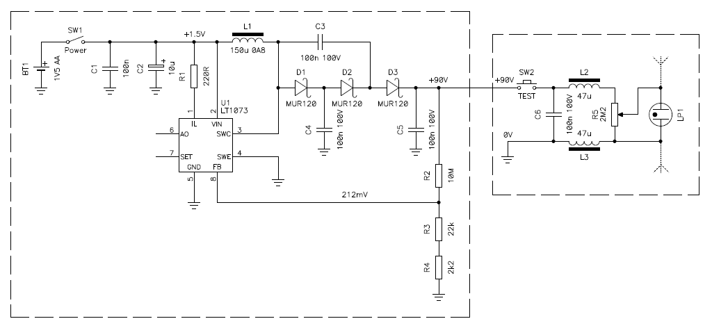
Circuit diagram of the RF field monitor with the safe high voltage
generator.
A voltage of 90 V should be enough for most glow lamps. If a higher voltage is required, reducing the value of R3 and/or R4 will increase the output. If this is not enough, one could try adding two extra MUR120 diodes and two extra 100 nF capacitors to the multiplier string, but I didn't test this.
I built this high voltage generator in a small plastic box together with a battery holder and a small output connector, so that I can use it to safely power any device requiring +90 VDC, the pulse generator described in the original article being one of those.
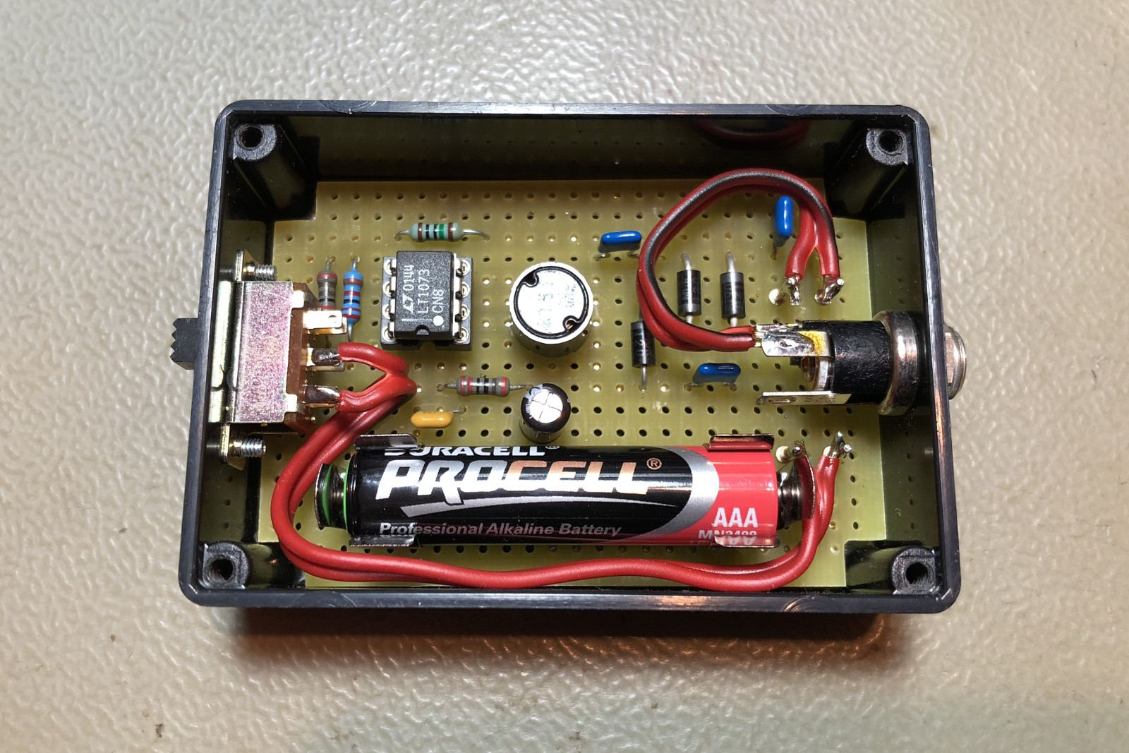
Picture of the safe high voltage generator. (click to enlarge).
Ionizing radiation can ionize a neon glow lamp. If you apply a DC voltage to a glow lamp that is higher than its maintaining voltage, but lower than its ionization voltage, the lamp should not turn on. But in practice, after a while, the lamp will eventually switch on by itself. What happens is that when an ionizing radiation goes through the lamp, it ionizes the gas and starts the discharge. Once lit, the lamp will keep glowing until the voltage is brought below the maintaining voltage. There are always a few ionizing radiations around, they are part of our environment and are called background radiation. There is nothing to worry about: unless you live in a contaminated area, background radiation is mostly a natural and normal phenomenon. But it can ionize your glow lamp; try it. How often it happens depends on the intensity of the radiation and on the lamp you have: maybe every few minutes, maybe every couple of hours, but it happens.
Neon glow lamps are not designed to be sensitive to ionizing radiation: they have some sensitivity but this is a side-effect and not a desired feature. According to [1], neon glow lamps can operate in high ionizing radiation areas: the lamps still work ok, but the glass can become brittle; of course, I didn't test this and I just report it as is.
I think it's interesting to have a look at a close cousin of the glow lamp: the Geiger Müller tube. It's also a low pressure gas discharge tube; it has two electrodes and a similar mixture of gasses. The pressure is higher, the electrodes have a much larger surface and the tube walls are much thinner to allow the ionizing radiation to easily enter the tube. In the picture below you can see a SI-8B (СИ-8Б) pancake style tube. It's particularly interesting because it has a large transparent mica window on one side that allows seeing what's happening inside; the large majority of Geiger tubes are made of solid metal and it's not possible to see through.
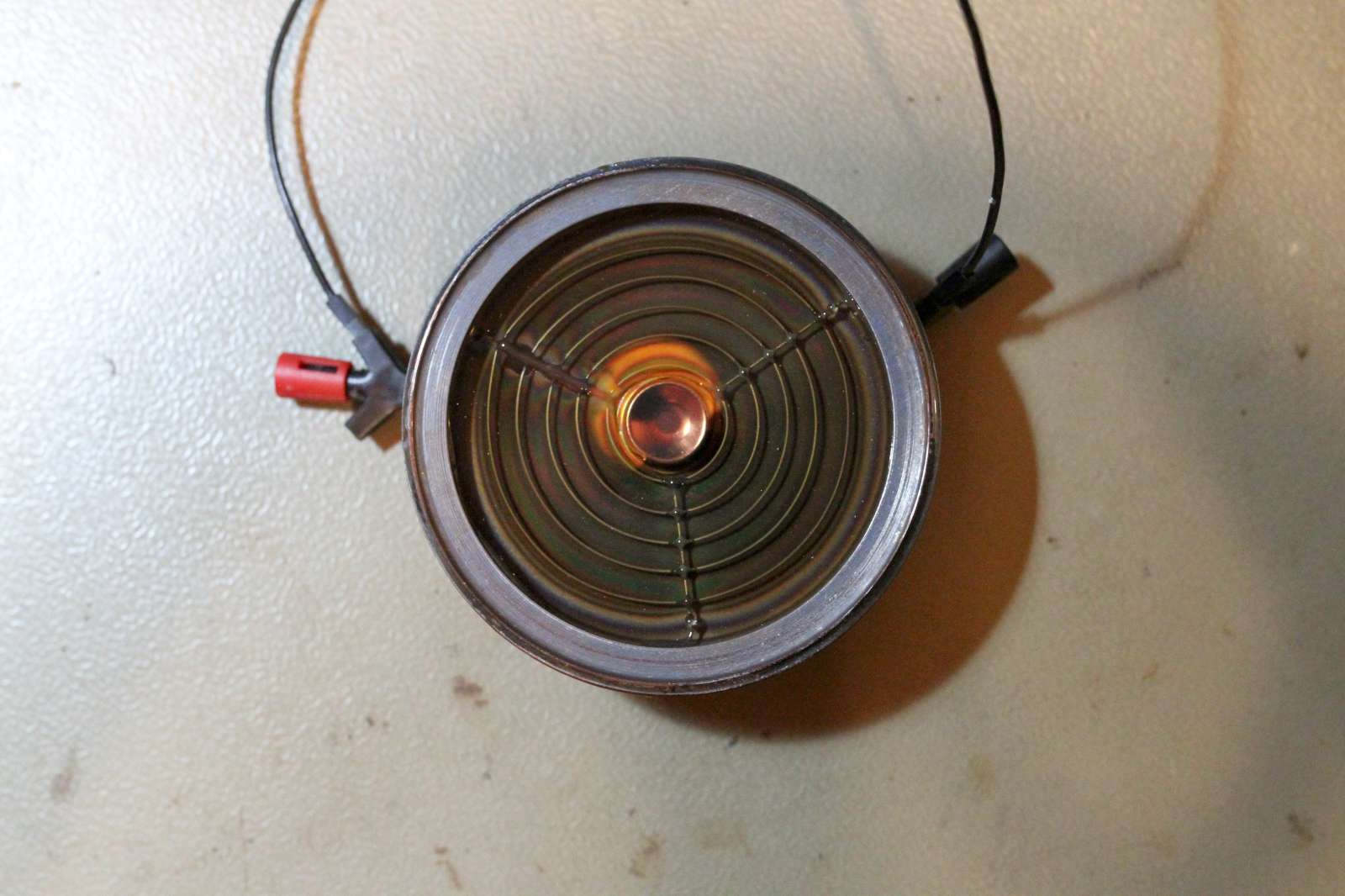
A SI-8B (СИ-8Б) Geiger tube connected to a suitable
power supply as specified in its datasheet: 390 V with a
4.7 MΩ series resistor. (click to enlarge).
Geiger tubes are operated just below their maintaining voltage in a region called plateau. They are not intended to steadily glow. When an ionizing particle enters the tube, it generates an avalanche discharge that amplifies its effect and makes the tube conduct for a short time. But the tube is designed to extinguish the discharge as quickly as possible to be ready to detect the next particle. It turns out that these discharges do generate some light, but because of the geometry of the electrodes and the low supply voltage, the glow is only localized in the area where the particle stroke. A general and steady discharge is to be avoided in Geiger tubes.
The following pictures give some examples. Because of the long exposures, more than one particle was detected and several glowing regions are visible in the same picture, even if they were separate events. The glow is really weak: it's quite hard to see with the naked eye even in complete darkness and you need to adapt your eyes to the darkness for several minutes before you can actually see anything. Taking a picture of these tiny flashes of light with a camera is even harder, so the quality of these images is not very good, but I hope they give the idea.
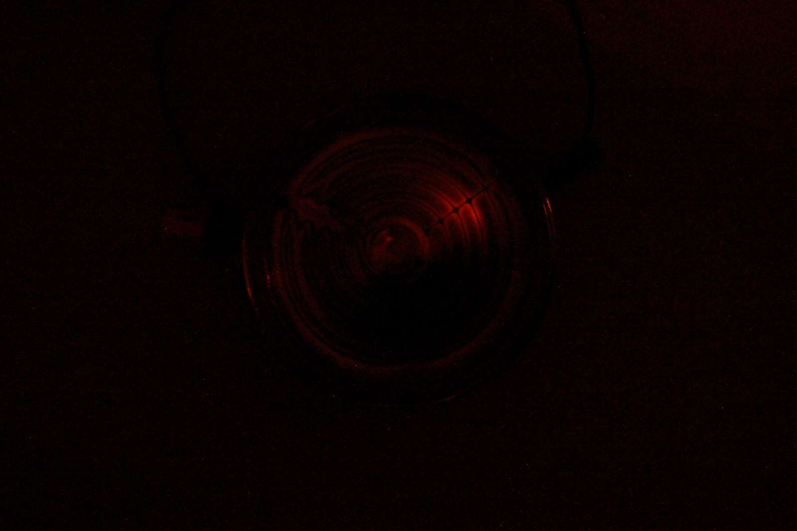
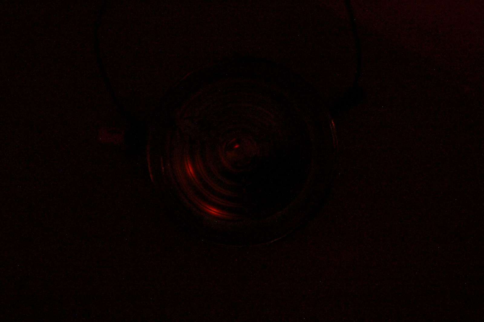
Several pictures of ionizing particles detected by the SI-8B tube
supplied with 390 V and a 4.7 MΩ series resistor.
Because of the long exposures, more than one discharge is visible in the same
picture, but they were separate events. (click to enlarge).
I presented in this page some aspects of neon glow lamps, trying to explain how they work and how to use them. Of course, if these lamps are not obsolete yet, they will be very soon. They belong to an era where it was common to supply electronics with several hundred volts and the active elements ware expensive vacuum tubes. Still, I find them fascinating devices that glow in a unique way and can do a little more than just generate light. Some circuits are really simple and common, others are quite unusual and more tricky, but definitely funny to build. Even the simplest circuit, a light bulb and a resistor, can be interesting enough to spend a whole evening in trying to find out what are the electrical characteristics and understand why it sometimes oscillates and sometimes not. I hope you’ll find this page interesting and maybe of some inspiration to have some fun in your lab. Again, let me warn you about the risks of the high voltage involved with these circuits: be careful, they are dangerous. Try them only if you know what you’re doing and at your own risk and don't forget to read my disclaimer.
| [1] | C. R. Dougherty, T. E. Foulke, J. D. Harnden, T. L. Hewitt, F. N. Peters, R. D. Smith, J. W. Tuttle. Glow lamp manual. 2ndedition, General Electric Company, Cleveland, OH, 1966. |
| [2] | William G. Miller. Using and understanding miniature neon lamps. Howard W. Sams & Co., Inc., Indianapolis, IN, 1969. |
| [3] | Nerio Neri I4NE. Nel mondo delle valvole. Ed. C&C, Faenza, 1992, pp 27-28 e 55-57 |
| [4] | Jim Williams. Application Note 45: Measurement and control circuit collection. Linear Technology, June 1991, page 18, fig 27, 1.5 V powered 350 ps rise-time pulse generator. |
| [5] | Atom Trace. Element Database. https://www.atomtrace.com/elements-database/ |
| [6] | Philip J. Kayatt. Flicker glow lamps. US patent 3238408, March 1, 1966. |
| Home | Electronics | Page hits: 201633 | Created: 07.1999 | Last update: 08.2024 |