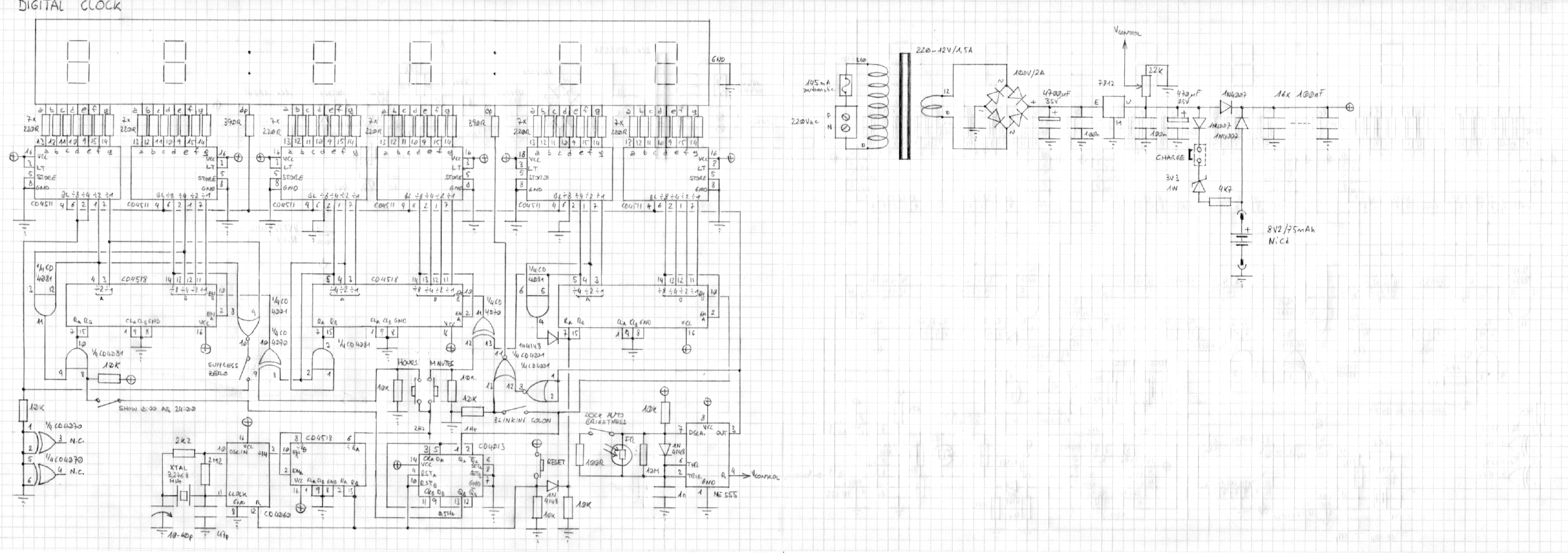
Circuit diagram of the C-MOS clock (click to enlarge). – A PDF version is also available: cmosclock-diagram.pdf (2,577,761 bytes).
It was in the early nineties, I was at high school and some lectures were really too boring to follow (or, should I say, the teachers weren’t good enough...). So, to avoid falling asleep, I started drawing flip-flops and dividers to sketch the circuit of a clock. Nothing to do with the lectures, probably history and biology, I'm not sure; but drawing circuits was much more interesting and challenging to do.
At that time I knew of many digital clocks published on various magazines and books, but they all used TTL 7400-series integrated circuits, and many of them used nixie tubes as display. I didn't want to use TTL because already at that time it was considered quite an old and power hungry technology. I remember a few projects with N-MOS or C-MOS technology, but they all used a dedicated IC, which is just a "black box" and is not interesting at all. I wanted to use C-MOS 4000-series integrated circuits instead. I wasn't aware of any similar circuit at that time, so I designed my own, and thanks to my boring teachers, I had plenty of time for designing it well. This doesn't mean this was innovative: at that time, plenty of other people had probably had the same idea before me; it just means it wasn't inspired on any similar project. An the advantage of doing his own design, is that you can fit in some cool features that the other clocks don't have.
If finished assembling this clock in autumn 1994, and it's running continuously and without interruption since then (and it still is). Now, 20 years later, I decided to create this page to describe this project that still gives me full satisfaction.
Instead of redrawing the circuit with some CAD software as I always do on this website, for this project, I decided to keep the original hand-drawn, pencil on grid-paper circuit diagram.
Circuit diagram of the C-MOS clock (click to enlarge). –
A PDF version is also available: cmosclock-diagram.pdf (2,577,761 bytes).
It all starts with a 3.2768 MHz crystal oscillating with a 4060 divider. Over the years, I had to adjust the 10–60 pF trimmer capacitor twice, say every seven or eight years, to compensate for crystal aging as the clock was running a few minutes per month too fast. An additional 4518 and 4013 generate three signals: one at 2 Hz used to manually adjust the time, one at 1 Hz used to count seconds and to make the second colon blink in sync, and one at 0.5 Hz used to delay the reset of the hours at the beginning of each day (more on this just below).
The 1 Hz signal goes through three 4518 double decade counters and six 4511 BCD to 7-segment converters that divide the pulses down in seconds, minutes and hours. Resetting minutes and seconds when the count reaches 60 is done with a 4081 AND gate. Hours are reset at 24 (no 12 hours operation for this clock) with two 4081 AND gates. Here, the 0.5 Hz signal comes in and, if the corresponding switch is closed, it delays the reset by one second: this makes a cool behavior of this clock that will display midnight as 24 and not as 0. In other words, the clock will display "23:59:59", "24:00:00" and "0:00:01". Opening the switch will remove this delay and reset the hours counter immediately. The hours leading zero can be suppressed with a 4001 NOR gate: if the corresponding switch is closed, when a zero is detected in the leftmost digit, the two most significant bits are forced high, and 4511 decoders turn off all their outputs when a number larger than 9 is present in their input, successfully blanking the digit.
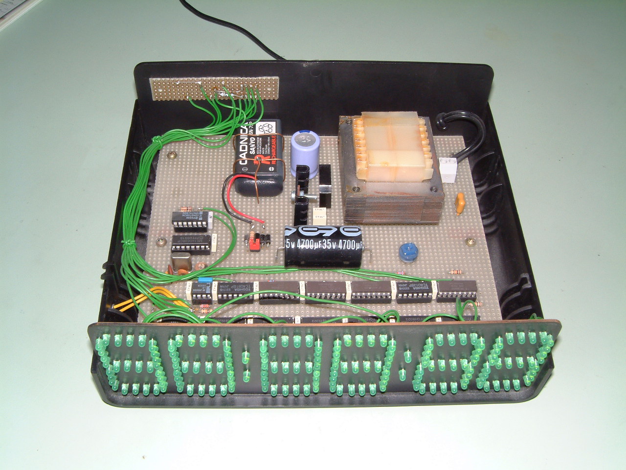
C-MOS clock, front view (click to enlarge).
Back in the nineties, small red LED 7-segment displays were common, but large green ones were very expensive. Since I wanted my clock to have a large green display, I built it by assembling strings of four green Ø3 mm LEDs in series on a PCB that I previously painted in black. The cathode of each string is grounded.
Since the display must be readable in all lighting conditions, to avoid being too dark during the day and too bright during the night, an automatic brightness control is also included. It's based on a 555 (ok, this is not a C-MOS IC) and a photo-resistor. It provides a PWM signal to the blanking inputs of each 4511 display driver (plus the two columns that are directly driven by the PWM). The 555 switches the display on for about 8 μs, and then it switches it off for a time that depends on the ambient light: between 0.1 μs (full brightness) and 10 ms (full darkness). The 10 MΩ resistor in parallel with the photo-resistor avoids that in full darkness the off time gets so long that the display starts to visibly blink. This automatic brightness control can be disabled by switching in a 100 Ω resistor in parallel with the photo-resistor, forcing full brightness regardless of ambient light. The photo-resistor should see just the ambient light but not the light emitted by the display: for this reason it's mounted on the side of the box.
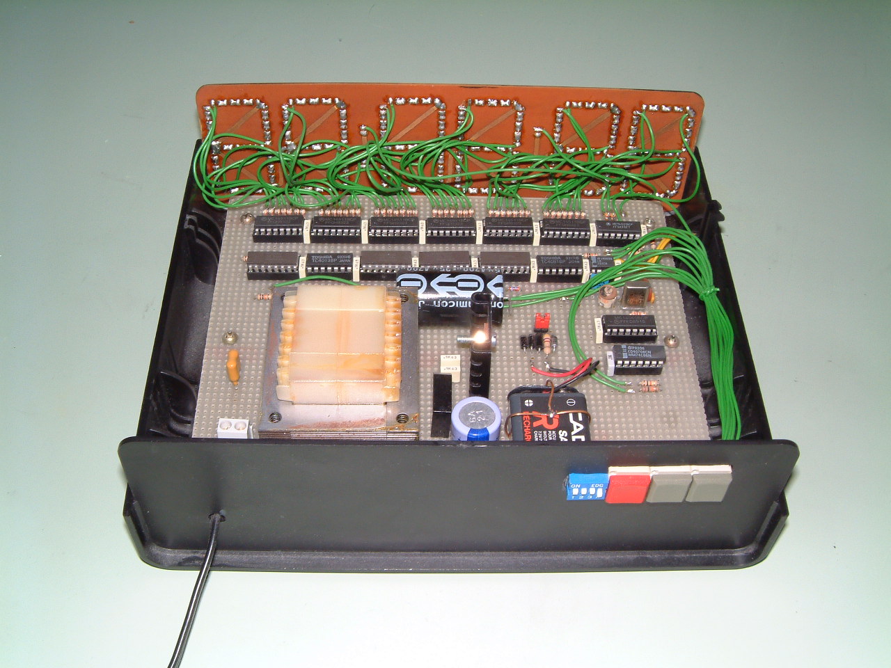
C-MOS clock, rear view (click to enlarge).
The correct time is adjusted by inserting a 2 Hz signal between seconds and minutes counters or between minutes and hours counters. This is done with 4070 two XOR gates and two push buttons. This solution is not ideal, because depending on the actual logic level on the XOR inputs, sometimes pressing the button has no effect and sometimes it counts twice. But it works well most of the times, and you don't adjust it very often. A third button is used to reset the seconds counter and all the dividers that generate the 1 Hz signal: this ensures than when releasing the button, the clock will start counting right away. To avoid problems, one should first adjust the seconds, than the minutes and finally the hours. Doing it in this order, if a button responds twice, it doesn't mess up the previous operations.
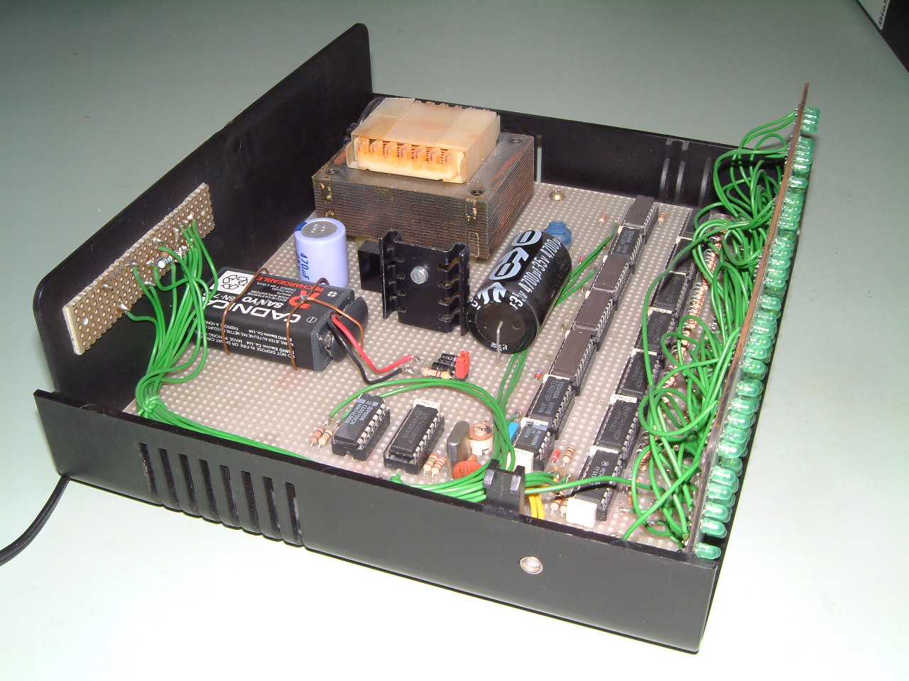
C-MOS clock, side view (click to enlarge).
All this circuit normally runs with 12 VDC provided by a small transformer, a rectifier and a 7812 voltage regulator. There is also a 9 V 6LR61 backup battery to keep the clock running in case of power outage. When no mains power is available, the voltage of the whole circuits drops from 12 V to about 8 V provided by the battery. All C-MOS ICs still work down to 5 V or less, so it's not a problem. The 555 driving the brightness of the display senses this condition through its RESET pin (labeled "VCONTROL") and shuts itself down turning off all the LEDs, drastically reducing power consumption. A 22 kΩ trimmer allows adjusting the voltage threshold and is set to switch the display off at about 10 V.
The initial design used a NiCd rechargeable battery, continuously charged via a 4.7 kΩ resistor and a 3.3 V Zener diode. I finally discovered that NiCd batteries only last for about seven or eight years when continuously kept under charge. I ended up replacing it with a standard non-rechargeable alkaline battery, which is much cheaper and last about as long. In this case, the jumper must be removed to prevent charging.
C-MOS clock, top view (click to enlarge).
Twenty years have elapsed after powering up this circuit for the first (and only) time. In the years there were many AC power outages and I moved it a few times, but because of the backup battery, it never stopped counting, second after second, the time going by. Today, this circuit looks quite old, and it wasn't the latest technology even when it was designed, but I think it's still interesting. After all, 20 years are more than 175'000 hours: a respectable fail-free running time!
| Home | Electronics | Page hits: 027520 | Created: 11.2014 | Last update: 11.2014 |