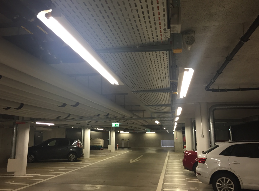
An underground parking with lots of fluorescent lights (click to enlarge).
Fluorescent tubes are everywhere; they are reliable and energy efficient. Even if today (2017) LEDs are replacing many light sources, tubes are still cost effective and have almost the same good efficiency, if not better. The old magnetic (inductive) ballast is nowadays often replaced with an electronic one for its better efficiency, but there are still so many old ballasts around that I think it's worth having a look at this simple and effective circuit.
An underground parking with lots of fluorescent lights (click to enlarge).
Finding detailed data on fluorescent tubes is very hard, and surprisingly enough, internet search engines are of little help. In spite of the large majority of electronic components where their manufacturers specify in great details all the electrical characteristics, for fluorescent tubes, it's difficult to find any datasheet with more than the nominal power and the mechanical dimensions. It's therefore very hard to answer questions like: what is the striking voltage? What is the burning voltage of the lamp? How does the current looks like when the lamp is on? I had these questions in my mind for many years, until I decided to hook up a lamp to a high voltage oscilloscope probe and have a look by myself at what is going on.
In order to make these measurements with an oscilloscope, some uncommon equipment is extremely useful (if not mandatory), like a high voltage differential probe and a current probe. Since not everyone has access to these tools, I decided to share my measurements in this page because I think they may be of some interest.
Direct connection of an oscilloscope to the mains is an extremely bad and dangerous idea, always use suitable and safe high voltage probes. Do not forget to read my disclaimer.
You will not find any rocket science technology in this page, just some measurements and some thoughts about fluorescent tubes, starters and their old inductive ballasts.
Only "hot electrodes" fluorescent tubes are discussed here; these are the tubes mainly used for lighting. They have two terminals per side to allow current circulating in the electrodes to heat them. On the other hand, "cold electrodes" tubes, also called CCFL (Cold Cathodes Fluorescent Lamps) like the ones used in "neon signs" only have one terminal per side: they have different electrical characteristics, require a different power supply system and are not discussed in this page.
The basic circuit is shown in the diagram below. Its behavior has been described many times in the literature and on the web, so here I'll only give a quick overview just to clarify what I'm talking about.
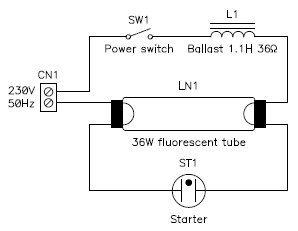
Schematic diagram.
The circuit is very very simple and is only composed by the fluorescent lamp, the starter and the inductive ballast.
It's important to remark that this circuit is typical for 230 V mains. In 120 V mains, the peak voltage is usually not high enough to keep the lamp burning and ballasts are often designed as autotransformers with a slightly different circuit [1]. Considerations on lamp voltages and currents will probably still apply, but the circuit, the ballast and probably also the characteristics of the starter are different. Since I never had the chance of playing with 120 V fluorescent equipment, I won't discuss it here and all the considerations in this page are only valid for 230 V mains.
This circuit lacks a phasing capacitor and will have a significant inductive reactance. This has been done on purpose to measure its cos(φ). Of course, in normal situations, a suitable circuit is added for compensation and bringing cos(φ) very close to 1. A capacitor in parallel with the mains line is often enough.
The fluorescent tube is generally composed by a glass tube containing a low pressure mixture of gasses, usually mercury vapor and some argon. The pressure is in the order of 5 mbar. Adding a small amount of noble gas(ses) to the mercury considerably lowers the striking voltage (Penning effect). At the tube ends are two tungsten filaments, similar to the ones of regular incandescent bulbs, that act as electrodes to transfer the current to the gas and are often called cathodes. Filaments are often coated with high electron emissivity substances, like barium compounds. A current flowing in these filaments will heat them up increasing their ability to emit electrons even more and therefore lowering the voltage required to ionize the gas and strike the lamp. This is why these elcotrodes have two terminals. When the lamp is on, the filaments stay hot enough with just the main lamp current and there is no need to force any additional current, so the other end of each filament can be disconnected.
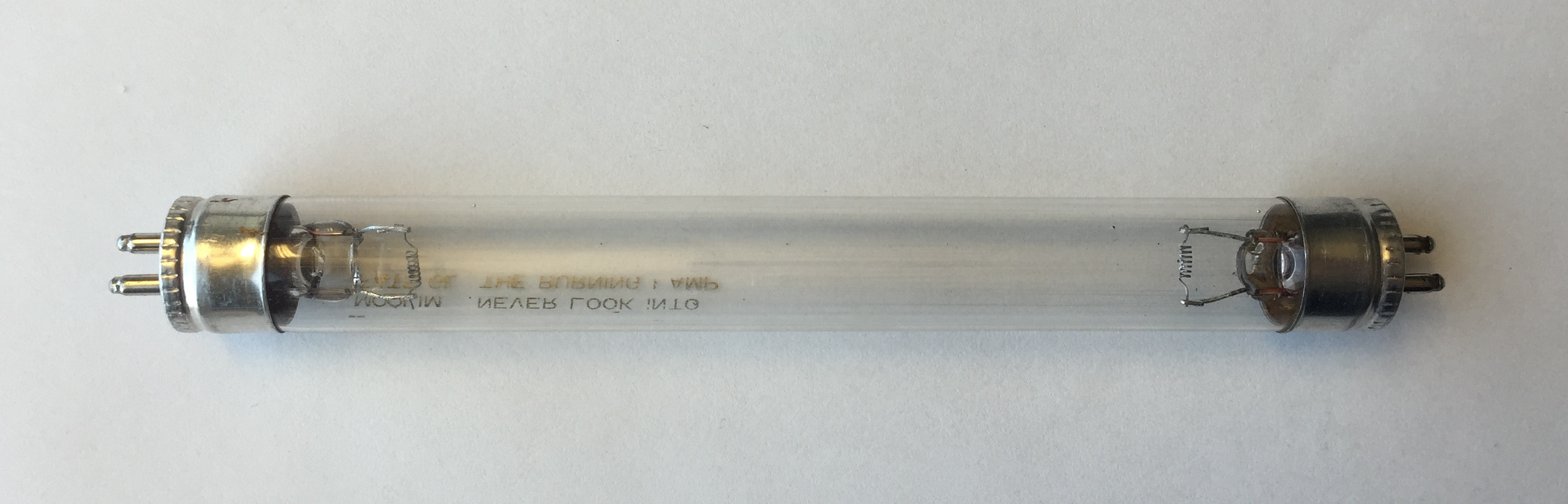
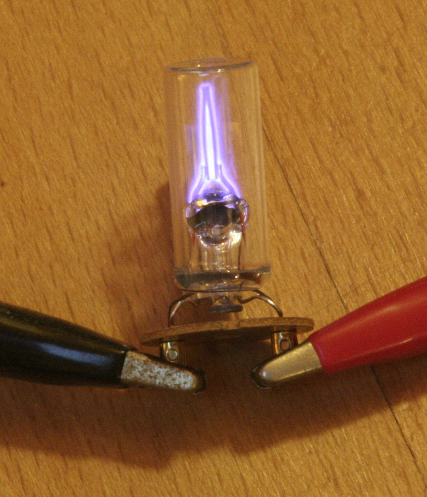
The internal structure of a fluorescent lamp is clearly visible in
this small transparent UV lamp, (click to enlarge).
By looking carefully at the large version of the image, small droplets of
mercury on the inside wall of the glass are clearly visible especially in
proximity of the electrodes.
Current flowing through a gas is a very complex phenomenon but, summarized in a few words, if the gas is not ionized, it behaves like an insulator. If a voltage large enough is applied between the electrodes, the gas ionizes and a current flows due to free electrons and positive ions (atoms that lost one electron) bouncing around. Chocks between electrons, ions and neutral atoms transfer some of the kinetic energy to the atoms that get "excited". The energy is then re-emitted as photons when they relax shortly after. The active gas in almost any common fluorescent tubes is mercury vapor: it emits light in the ultraviolet (UV) range which is both invisible and harmful for our eyes and skin. A coating of fluorescent materials inside the tube absorbs this UV light and converts it into visible light. By carefully selecting a suitable fluorescent coating, almost any color of light can be obtained. Furthermore, the glass composing the tube is not transparent to the UV radiation and prevents it from escaping outside.
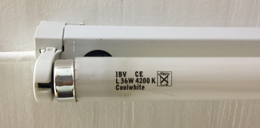
The tube used for these tests, IBV L36W 4200K, (click to enlarge).
For these measurements, I used a IBV T8 (Ø25.4 mm) tube, 4' (1.2 m) long, 36 W, cool white. On this particular lamp, the DC resistance of its two filaments is 5.9 Ω and 5.3 Ω, when cold. I also measured a bunch of other tubes and found similar values: a few Ω.
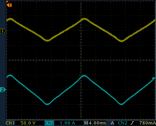
The two following plots shows the voltage and the current in a burning lamp. Of course, an inductive ballast is connected in series. Please remark that here the lamp is already on and its filaments are hot due to the lamp current.
In the first plot, where the voltage and the current are represented separately, it's interesting to remark that both are in phase, even if not perfectly sinusoidal shaped. This shows that the lamp is effectively absorbing active power. It's also worth noting that the voltage is close to a square wave. This is typical of gas discharge tubes that have a very similar behavior as a Zener diode, where the voltage is about constant regardless of the current. By looking closer, one can see that actually the voltage drops slightly as the current increases (the square wave is not perfectly flat but lowers a bit in the middle, when the current is at its maximum). This shows a negative resistance behavior, another typical characteristic of a gas discharge tube. In a normal resistor, if the current increases, the voltage drop also increases; here it's the opposite.
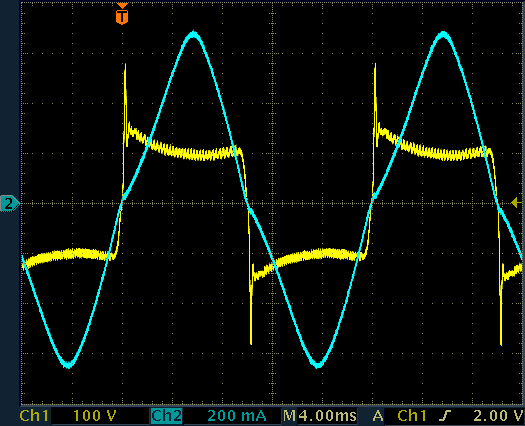
Lamp voltage (CH1) and lamp current (CH2) of a burning 4' (1.2 m) T8 (Ø25.4 mm) 36 W tube.
At the end of each half cycle, the current drops to zero and the lamp extinguishes. As soon as this happens, the lamp strikes again, a pulse of opposite polarity appears on the plot and the cycle repeats. This pulse is not due to the inductive ballast (as the current was already zero), it's just the mains voltage that restrikes the tube: this works because the filaments are still hot (more details here).
The voltage waveform is not perfectly smooth: there are small ripples of oscillations, about 20 Vpp at 4 kHz in this case. This is another typical behavior of a negative resistance and of a gas discharge tube. Even if I didn't do any further measurements on this, it should not be a problem for this circuit as the amplitude and the frequency of the oscillations are low enough to be a concern for electromagnetic compatibility.
The same measurement can be shown in XY mode (below), where on the X-axis there is the lamp voltage and on the Y-axis the lamp current. The point with zero voltage and zero current is in the center of the grid. When the lamp is on, the voltage is around 100 V (positive or negative). The stray oscillations are also visible.
One interesting fact to remark is that the lamp current slightly increases even before the lamp strikes. On the plot, there not a perfectly horizontal line but more a tilted "S": as the voltage increases, as small current flows straight away. I'm not sure about this, but I think it's due to the hot electrodes and the gas still being partially ionized that allow some current flow. Then, of course, as the lamp strikes, the current suddenly increases and the voltage drops around 100 V.
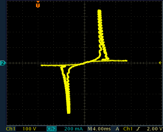
Lamp current (vertical) as a function of voltage (horizontal) of a burning 4' (1.2 m) T8 (Ø25.4 mm) 36 W tube.
It would be interesting to perform the same measurements with a cold lamp and see what it takes to strike it without preheating the filaments. Unfortunately I don't have a suitable high voltage AC source, enough to strike the lamp.
The inductive ballast is just a big inductor wound on a laminated iron core. It has two functions: it limits the current and generates the high voltage to strike the lamp. Fluorescent tubes have a negative resistance characteristics and therefore cannot be directly connected to the mains. In other words, if the current in the lamp increases, the equivalent resistance decreases, further increasing the current. The ballast limits the current and prevents the lamp from self-destruction.
Inductors work very well as lamp ballasts: on one hand the inductance prevents the current from jumping abruptly and prevents high current spikes from damaging the electrodes. On the other hand the inductance (in conjunction with the starter) can also easily generate the high voltage pulse required to strike the lamp. But they have some drawbacks: they are expensive (they require a lot of copper), they are heavy (they have a lot of copper and a lot of iron) and they are not very efficient (a long winding has resistance). But they are simple and reliable; if you have a 70 years old ballast it's very likely that it's still in perfect working conditions.
Inductive ballasts are inductors and therefore are frequency dependent. A ballast designed for 50 Hz will have too much reactance at 60 Hz and vice versa.
Low power lamps (a few Watts) may also just use a simple resistor; in this case the high voltage pulse is just due to the mains wiring stray inductance. Surprisingly enough this works, but only for relatively short tubes. The downside is that the resistor converts into heat about the same amount of power as the lamp, resulting in very bad efficiency. I've seen this only once in a garage inspection lamp where the 5 m long power cord has thin nichrome wires instead of copper wires and becomes warm when the lamp is on.
Capacitive ballasts would have significant lower losses and would be a lot cheaper, but because of the nonlinear behavior of the lamp, this would generate very high peaks in lamp current. In other words, when the lamp strikes the voltage suddenly drops and the charge stored in the capacitor is suddenly dumped into the lamp. This generates a very high current pulse that is hard on the lamp electrodes and has a tendency to damage them. Because of the negative resistance of the lamp it has a tendency to take almost all the charge in the capacitor and extinguish, the capacitor recharges again and the cycle repeats many times per AC cycle resulting in lamp instability and flickering. Furthermore, capacitors cannot generate the high voltage peak required to strike the lamp, so it only works for very short lamps [2]. Even if capacitive ballasts are a bad idea, they are sometimes used in cheap bug zappers, garage inspection lamps and applications where nobody really cares about the life or the cost of the lamp.
On the other hand capacitive ballasts are only (and often) used in high frequency electronic ballasts where the capacitance is low and the frequency is high. The low capacitance ensures that there is not much charge to dump into the lamp and the high frequency ensures that the lamp has no time to be unstable.
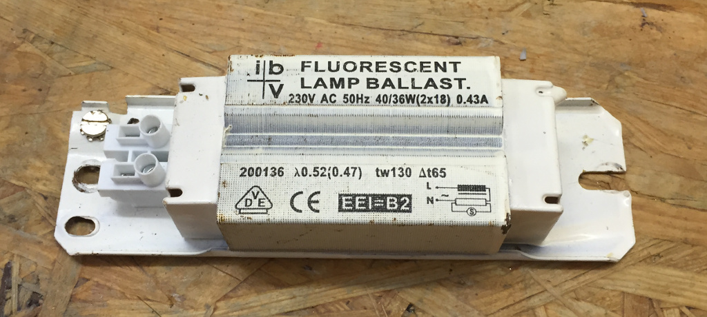
Picture of the inductive ballast used here, IBV 230V AC 50Hz 40/36W (2×18) 0.43A (click to enlarge).
The ballast used here is rated 230 V, 50 Hz, 40/36 W, 0.43 A. I measured an inductance of 1.097 H and a series resistance of 36.8 Ω when cold.
With this impedance, if shorted on the mains (assumed to be 230 V 50 Hz), this ballast will limit the current at 0.66 A dissipating 16.2 W. This is outside its specifications and may overheat, but for sure it won't be a dead short.
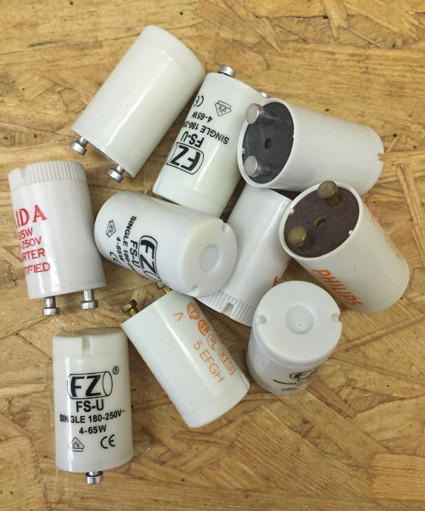
A bunch of old starters. The one used here for testing is the one on
the bottom left, FZ FS-U 180-250V~ 4-65W (click to enlarge).
The starter is composed by a small glass tube filled with a mixture of low pressure noble gasses, usually argon, neon and helium under a pressure in the order of 50 mbar [3]. Inside the tube are two bimetallic electrodes that bend toward each other when hot. When cold, the two electrodes are close together but do not touch. As a high enough voltage is applied, the gas ionizes, a current of about 30 mA starts flowing, and the gas glows. After about half a second, the heat generated by the glow gently bends the electrodes that touch, short together and the glow extinguishes. When hot, a starter behaves like a short-circuit. Since a shorted starter is not glowing anymore, it cools down and the contacts open again in about half a second.
Watch a movie showing the starter glowing and the electrodes shorting:
glowing-starter.mp4
(1,870,811 bytes, 14 s, H264,
640 × 480, 15 fps).
With a starter and a light bulb, you can make a very nice and crude blinker.
The starter used here is a FZ FS-U, rated 180-250 V~ 4-65 W. To better understand the starter characteristics, its current as a function of the applied voltage has been measured and is visible in the trace below:
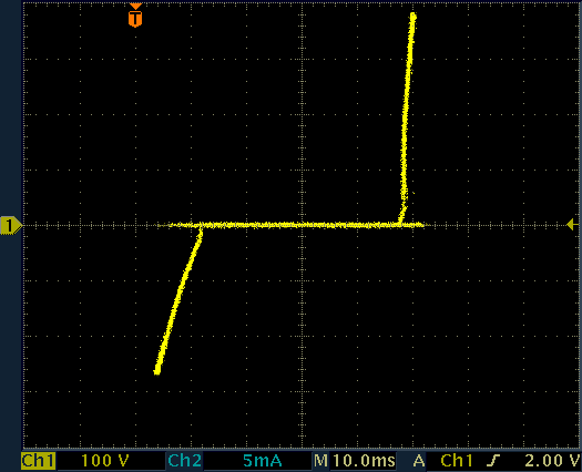
Starter current (vertical) as a function of voltage (horizontal) for the FZ FS-U starter.
On the horizontal axis is the applied voltage, on the vertical axis the resulting current. Zero for both axis is in the middle of the screen. Starting from zero, as the voltage is increased (in either positive or negative direction), no current flows through the starter, resulting in the horizontal line. As soon as the voltage is high enough (say +220 V or −240 V in this case), the gas ionizes and becomes conductor; the voltage drops by about 50 V and a current starts flowing (slanted segments). If now the voltage is decreased, the current also decreases until the minimum burning voltage is crossed (say ±180 V in this case) where the current drops to zero (back on the horizontal line).
For taking this measurement you have to be quick: as soon as the starter is hot, it will short out and you will only measure a vertical line. You have to take a screenshot while the starter is still glowing (heating up).
The behavior of this (and almost any starter I had the chance to measure) is not symmetrical. Threshold voltages and dynamic resistance (the slope of the slanted segments) are not the same for positive and negative polarities. I think is due to the unsymmetrical shape of the electrodes.
Very often there is a polystyrene capacitor connected in parallel to the starter which helps reducing the switching noise. Unfortunately, I've never seen any marking on these capacitors, but they usually measure around 5 or 6 nF. To take the above measurement, this capacitor was temporarily removed, otherwise the segments look more like ellipses.
The gas in the lamp is normally an insulator. To switch it on, the electrodes are preheated for a few seconds, then a high voltage pulse will ionize the gas inside the tube and start the lamp. This process follows the following steps:
The power switch SW1 is open and the lamp is off and cold. Both the lamp LN1 and the starter ST1 are not ionized and behave like insulators. Not very interesting so far... Now, we close SW1 and apply power to the circuit.
SW1 is closed and, through the ballast L1, the mains voltage appears across the lamp and the starter which are in parallel (through the heating filaments). The mains voltage is not high enough to ionize the gas in the lamp which still behaves like an insulator, but is enough to ionize the gas inside the starter, which behaves roughly like a neon glow lamp. A small current now flows in the circuit and heats up the starter. This can often be observed as the starter usually glows with a faint blue light.
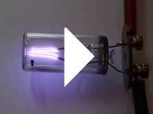
A starter glowing while heating up (click to enlarge).
In this phase, a current of 38.5 mA was measured. Too low to preheat the electrodes in the tube, that remain dark; only the starter is glowing. Because of the inductance of the ballast, this current is reactive: a cos(φ) of 0.79 was measured, corresponding to an angle φ of 38°. With a mains voltage of 237 V, the total apparent power is 9.1 VA and the active power is 7.2 W.
The length of this phase is somehow erratic and depends on many factors like mains voltage, ambient temperature, starter age and so on, but it's in the half a second range. The one measured here was 550 ms long.
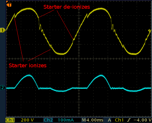
Lamp (starter) voltage and current while the starter is heating up
(glowing).
The traces abve show the voltage across the starter (and therefore also across the lamp) during this phase. The glitches in the voltage sine wave indicate at each cycle exactly when the starter starts glowing and when it switches off. Here, the starter ionizes at around 230 V and deionizes at about 180 V. Of course, every half AC cycle, the voltage goes to zero and the gas in the starter deionizes. It will ionize again in the next half cycle as soon as the voltage is high enough. The current trace (in blue) shows that the conduction of the starter is not symmetrical: positive peaks have higher current than negative ones. I don't know for sure why this happens, I suppose it's due to the unsymmetrical shape of the electrodes inside the starter. In any case, this current is small and is only used to heat the starter: it doesn't need to be symmetrical.
The starter heats up and the bimetallic switch inside it eventually closes. Now the starter is a short circuit, stops glowing and starts to cool down. As the starter closes, a larger current flows through the lamp filaments that are now connected in series though the shorted starter and they heat up. Heating the tube electrodes significantly lowers the lamp striking voltage. By the way, for this reason, starting cold lamps in a cold environment is much harder that restriking hot lamps. So, the filaments are now glowing red hot and this reddish light can often be observed on the tube ends during this phase. Because of the high emissivity of the electrodes, a (white) glow of the fluorescent coating of the tube ends is often observed as well.
During this phase, the current is 589 mA. A cos(φ) of 0.23 was measured, corresponding to an angle φ of 77°. With a mains voltage of 236 V, the total apparent power is 139 VA and the total active power is 31.5 W.
Lamp voltage and current while heating (the starter shorted), measured
across both filaments in series.
Both filaments are now in series and share the same current and half the voltage. The RMS voltage across each filament is about 11 V. Each filament gets about 6.5 W so, out of the total 31.5 W, 13 W heat the electrodes and 18.5 W are wasted in the ballast. Current and voltage in the filaments are in phase, the low total cos(φ) is only due to the reactance of the ballast.
As before, the length of this phase is also somehow erratic and depends on many factors, but it's also in the half a second range. The one measured here was 400 ms long.
As the starter cools down, the bimetallic switch opens again interrupting the current. As inductors don't "like" sudden current variations, the ballast answers to this interruption with a high voltage spike that will most probably ionize the lamp and light it. Since the exact moment when the starter opens cannot be controlled in this circuit (it's determined by the cooling of the starter, its age, the overall temperature,...), it may happen in an unsuitable moment of the AC cycle, when current is already quite low; a low voltage surge will result and the lamp may not strike. Should this happen, the full mains voltage will appear again on the starter and the whole process will start again from step one. Old and cold lamps also require a higher voltage and are more difficult to strike.
High voltage striking pulse (−2.78 kV).
Some stray high voltage pulses are also visible before the lamp strikes and
are due to bad starter contacts.
Striking pluses are very variable. They don't always strike the lamp, can be positive or negative and strongly depend on the time of phase relation at opening which is a thermo-mechanical process and is not synchronized with the mains frequency. Other factors influencing the amplitude of the pulses are the speed at which the bimetallic electrodes break, the gas filling in the starter, its age and maybe others. The one shown here is −2.78 kV, but pulses between 1 and 3 kV, both positive and negative have been observed with this same setup (lamp, starter and ballast).
When the lamp strikes, the voltage across it will drop, and this particular tube holds a voltage around 100 V. Every half AC cycle the current drops to zero and the lamp has to restrike every time. Because of the phase shift introduced by the inductive ballast, when the current crosses zero and reverses, the voltage is not zero so that the lamp can immediately restrike with just the mains voltage, as long as the lamp is hot and the gas is not deionized for too long, no additional high voltage pulses are required. If the lamp is turned off, the electrodes will cool down and almost all the ions in the gas recombine: now a new starting sequence is required to restrike the lamp.
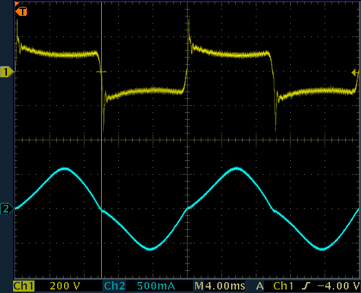
Voltage on the starter (and also the lamp) and lamp current when the lamp is on.
The trace in the figure above shows that lamp current and lamp voltage are in phase, which makes sense because the lamp is consuming active power. The mains voltage is not shown here (unfortunately, I don't have two high voltage probes), but is out of phase because of the reactance of the ballast. In other words, lamp current and lamp voltage are in phase, but because of the ballast, lamp current and mains voltage are not. Every time the lamps turns off (current goes to zero), the voltage immediately jumps to more than 300 V in the opposite polarity. This is just the mains voltage appearing on the lamp. Because of the significant phase shift of the ballast, the mains voltage is close to its peak when this happens explaining the sudden spike. As the tube is now hot (and has probably also a lower striking voltage than the starter) it will strike first, quickly bringing the voltage back to the burning voltage (around 100 V) and preventing the starter from glowing.
Should the lamp turn off, the voltage will rise and the starter will ionize starting all over from step one. This is what happens with old or damaged tubes that continuously flicker in the "hope" of turning on again one day.
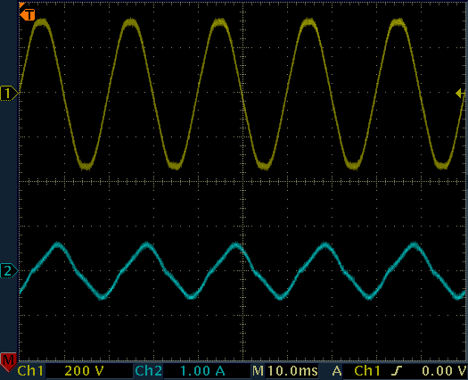
Mains voltage and current while the lamp is on. Phase shift is clearly visible.
With a mains voltage of 236 V, the total current is 385 mA and the cos(φ) is 0.49, corresponding to an angle φ of 60°. The apparent power is 90.9 VA and the active power is 44.9 W. The power lost in the ballast is 5.5 W and the tube absorbs 39.4 W leading to an efficiency of 88%: quite good for such a simple circuit. A higher efficiency can be achieved with a better inductive ballast (built with more copper and more iron to minimize its losses) or with an electronic ballast. Of course (and unfortunately) the lamp cannot convert all the energy into light.
Now that we went through all the steps of the striking sequence, let's summarize it and have a look at what happens in a more general way. In the trace below, the voltage on the starter can be observed:
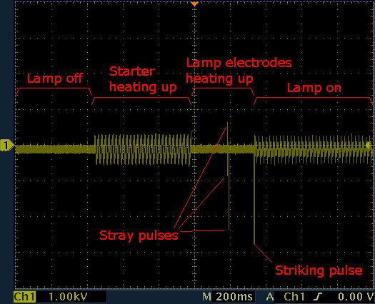
Voltage on the starter (and also the lamp) during all the starting
process.
Because this measurement is taken on the starter side of the filaments, the
heating voltage is not visible and appears as a short.
The different steps are clearly visible. At step zero (lamp off) there is no voltage. When SW1 is closed (step one) the starter ionizes and start to heat up. After about half a second the starter shorts out (step two) and the lamp electrodes start to heat up while the starter cools down. Since the lamp is shorted by the starter, the voltage on the starter side of the filaments, as measured here, reads zero. Of course, there is voltage on the filaments that are now glowing, but cannot be observed here. After another half a second the starter is cold again and opens (step three) generating a high voltage surge that strikes and switches on the lamp (step four).
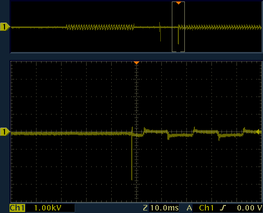
It's also interesting to look at the voltage on the ballast (below), where these same steps can be observed again. Please remark, that this measurement was taken on the same equipment but a few minutes later, therefore the duration of the different steps is different.
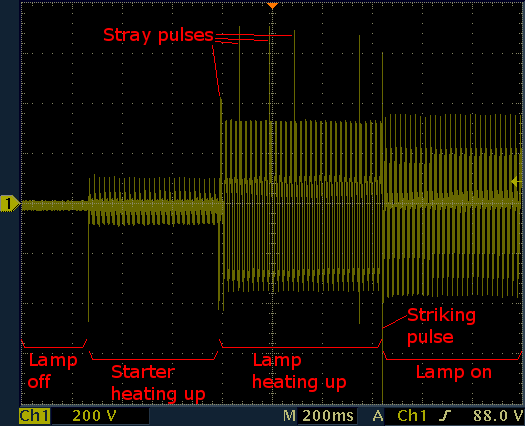
Voltage on the ballast during all the starting process.
The amplitude of this voltage gives a rough idea of the current flowing in the circuit.
Stray pulses are present while the starter is supposed to be shorted. This means its contacts are not perfectly reliable and sometimes it opens for a tiny fraction of a second. Even if these pulses are strong enough to strike the lamp, this doesn't happen because as the contacts close again, the lamp is shorted and cannot switch on. It will only switch on after the last pulse, when the starter finally opens and stays open. Stray pulses do not harm and the circuit works fine.

Watch a movie showing the full striking sequence:
fluorescent-tube.mp4
(3,781,910 bytes, 11 s, H264,
960 × 540, 24 fps).
We discussed so far how the lamp is started and its electrical characteristics. Let's now have a look at some other considerations, like the power factor or the spectrum of the light.
Because of the inductance of the ballast, this circuit has a bad power factor: I measured a cos(φ) of 0.49. Since all loads connected to the mains should have a cos(φ) as close as 1 as possible, something should be done to improve it. There are several different solutions to this problem, but the simplest one (and the only one discussed here) is just to connect a suitable capacitor in parallel with the mains.
To find out the required capacitance, we first need to calculate the reactive power that we need to compensate. We found earlier that the apparent power S is 90.9 VA while the active power P is 44.9 W. If you wonder how to measure them, determining the apparent power is quite easy: just measure the mains RMS current (here I = 385 mA) and voltage (here U = 236 V) with a multimeter and multiply them together: S = U · I = 90.9 VA. Finding the active power is more tricky: if you have an AC power meter it will give you P right away, and this is what I did. If not, you could measure the phase angle φ either with an oscilloscope (as I did, too) or with a cos-phi-meter (if you have one) and then calculate P = S · cos(φ). But if you don't have this fancy equipment, you can still use the three voltmeters method.
Knowing S and P, you can calculate the reactive power Q with the formula below. It's a pity that in electronics le letter Q is used for both the reactive power of an AC circuit and for the quality factor of an LC circuit: in this page Q is the reactive power.
This is nothing more than the Pythagorean theorem, where S is the hypotenuse and P and Q are the other two sides of a right triangle. With the values of S and P that were measured before, we find Q = 79.0 var.
As a reminder, the active power P is measured in Watts (W), the apparent power S is measured in Volt-Amperes (VA) and the reactive power Q is measured in Volt-Amperes-reactive (var). This is just to differentiate them and avoid confusion, even if physically all these three units have the dimension of power.
To compensate this inductive reactive power, we introduce an equal amount of capacitive reactive power, with a capacitor in parallel to the mains. The reactance X producing such reactive power is given by:

Where U is the mains voltage. We find X = 705 Ω. Finally, with determine the required capacitance C with the following equation:

Where f is the mains frequency (50 Hz in this case). We find 4.5 μF. This capacitor must be rated for direct connection to the mains voltage: use only class X1 or X2 capacitors.
Inductive ballasts are not the only ones available. The simple series inductor only works for mains voltages of 230 V. In countries with mains voltages of 120 V, depending on tube length and power, the voltage may be too low to keep the lamp burning, so ballasts are slightly different and work as an autotransformer to step up the voltage and limit the current at the same time.
Some autotransformer type ballasts may also work without a starter, with or without electrodes heating. The high voltage pulse required to strike the lamp can be generated by a resonant circuit composed with an additional capacitor. Additional windings in the ballast can be used to preheat the filaments if required [1]. Starting a tube without preheating the filaments is possible, but the higher voltages required usually causes sputtering on the electrodes that wears out prematurely.
Nowadays, electronic ballasts are replacing the old inductive ones, especially for their higher efficiency, better startup properties and the ability to dim the light. By the way, dimming a fluorescent tubes with an inductive ballast is possible to some extent, but when dimmed below a given threshold the main current is too low to keep the filaments hot enough and an additional heating current must be circulated in the electrodes, for example with an additional transformer. It's unfortunately not possible to dim down to 0%.
As explained above, the light emitted by fluorescent tubes is normally converted from ultraviolet to visible radiation by a mix of fluorescent pigments. When observed with a light spectrometer, the emitted spectrum is not continuous as the one of an incandescent lightbulb, but is composed by several peaks, each one corresponding more or less to a specific pigment. This explains why some objects appear of a different color under fluorescent lighting.
Moreover, the some peaks appear and tell us about the gas present in the tube. For example, by looking at the spectrum of the cold white IBV L36W 4200K tube that we already considered before, we see that it contains mercury, argon and neon. Accounting for the low precision of my simple spectrometer, we clearly recognize the spectral lines of mercury at 365, 405, 436, 546 and 577 nm. The peak measured at 808 nm is certainly due to argon that emits at 810 nm, while the one at 875 nm is certainely due to neon that emits at 878 nm. For the other peaks, a better spectrometer would help: we measured peaks at 757, 827, 848 and 890 nm: argon emits at 752, 826, 852 and 885 nm while neon at 754, 827, 850 and 887 nm. Hard to tell which is which. But we know that both gasses are present from the peaks at 810 and 878 nm. The bell-shaped emission between 400 and 700 nm is the due to the phosphor coating that excited by the UV emission of mercury and account for most of the white light produced by this tube. Reference spectral lines can be found in [4].
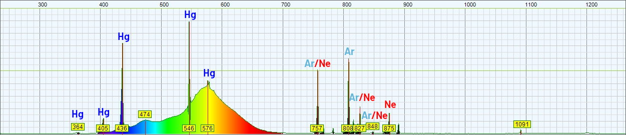
Spectrum of the emitted light of an IBV L36W 4200K cold white tube.
For comparison, I also measured a warm white tube. This is a Philips TL-D 36W/827 rated for a warm 2'700 K light. It's spectrum is completely different. We still see the presence of mercury by the peaks at 405, 436 and 546 nm, and the presence of neon by its peaks at 585, 610, 633 and 651 nm. The emission of the fluorescent coating is "bumpier&guot; and explains why this light has a lower color rendering index.
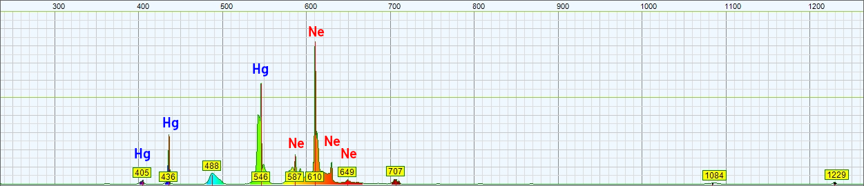
Spectrum of the emitted light of a Philips TL-D 36W/827 warm white tube.
On the horizontal axis is the wavelength in nanometers, on the vertical axis the intensity of the light in an arbitrary but linear unit. This particular tube has a cold white coating and is rated for a color temperature of 4'200 K.
Some measurements and considerations about (hot cathode) fluorescent tubes have been presented. There is no rocket science in this page, but just some unusual electrical information about fluorescent tubes and their glow starters. I hope you'll find it useful.
| [1] | A. Daeschler, G. Camponovo. Elettrotecnica. Edizioni Casagrande SA, Bellinzona, 1974, sezione 11.3. |
| [2] | Technical application guide - fluorescent gear. Philips Lighting, 2006. |
| [3] | Guide to starters. OSRAM GmbH, 2010. |
| [4] | Atom Trace. Element Database. https://www.atomtrace.com/elements-database/ |
| Home | Electronics | Page hits: 054547 | Created: 04.2017 | Last update: 08.2024 |