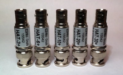
Sooner or later every ham needs a fixed attenuator. Even if the main reason is still reducing signal power, there are several other reasons why a attenuators are useful: for example one would use an attenuator for very broadband impedance matching. The bandwidth is only limited by the quality of the resistors used and their mechanical assembly. Another reason for using an attenuator is for hiding an impedance mismatch of a wired load such a diode power meter (which has non-linear impedance). Putting an attenuator in-between will reduce the mismatch by twice the attenuation factor in dB (for example a short circuit behind a 10 dB attenuator will result in a return loss grater than 20 dB which is equivalent to a VSWR lower than 1.22:1).
There are basically two kinds of fixed attenuators that can accept the same impedance on both sides: Π and T attenuators. Both achieve the same result but depending on the desired attenuation one may have more reasonable resistor values. O and H attenuators are symmetrical versions of Π and T respectively. If input and output impedance are equal any attenuation can be obtained. If not, a minimum attenuation is required in order to match the impedances.
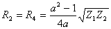
The bridged T attenuator (T) is a special version of the Π attenuator which is normally preferred when designing variable attenuators (for example with PIN diodes). The reason is that there are only two variable resistors which can assume any value from 0 to infinity. Unfortunately this attenuator requires that the input impedance equals the output impedance and therefore no impedance matching can be achieved (at least with the equations used in this script).
Following is a brief summary of the equations used to compute attenuators:
Π attenuator:
 ;
;
 ;
;
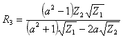
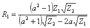
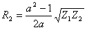
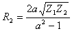
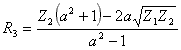
T attenuator:
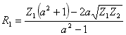 ;
;
 ;
;
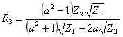
T attenuator:
 ;
;
 ;
;
 ;
;

O attenuator:
 ;
;
 ;
;
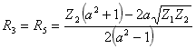
H attenuator:
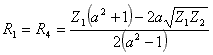 ;
;
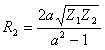 ;
;
Attenuation:

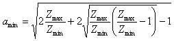
Minimum attenuation:
| Home | Electronics | Page hits: 067626 | Created: 11.2005 | Last update: 11.2005 |