Meters with W and A readings. – A PDF version is also available: meter.scale.pdf (7,307 bytes).
The meter unit is in charge of displaying three important parameters of the transmitter: forward power, reflected power and final amplifier supply current. If the reflected power or the supply current is too high, an alarm condition is reported to the driver unit to immediately shut down the transmitter preventing (hopefully) the MOSFET from blowing up. This happen quite often: if something is wrong with the antenna and the reflected power is too high, the operator reaction is not fast enough and one or more power MOSFET will usually die in a fraction of a second. This automatic shut-down feature saved the life of the final transistors several times (even if they can still blow up).
Forward and reflected power information is measured by a directional coupler in the TX/RX switch unit and consists in two analog voltages function of the power. Actually, because P = U2/R, the function is non-linear and the scale of the meters has been redrawn to have a direct reading in Watts. To have an idea, 1 kW of power through the coupler will produce a voltage of about 13 V.
Meters with W and A readings. –
A PDF version is also available: meter.scale.pdf (7,307 bytes).
These two voltages enter this unit via connectors CN1 and CN2, trimmers R1 and R5 are used to divide them down and adjust the reading on the analog μA-meters M1 and M2. Use 20-turns precision trimmers. Diodes D1, D2, D4 and D5 protect the meters from over-voltages.
The current is sensed and converted to a voltage in the final unit and arrives here via CN6. To have an idea, 10 A of current will generate about 1.2 V. R8, D6, D7 and M3 work in the same way as before, but here the relation between current and voltage is linear and there is no need for a complicated scale.
Circuit diagram of the meter unit (click to enlarge). –
A PDF version is also available: metercircuit.pdf (36,202 bytes).
U1 is an LM393: a good old double comparator. It's used to monitor the reflected power and the amplifier current information and make sure they are below the given thresholds. The meters used here have 100 μA full scale reading and an impedance of about 1.2 kΩ, meaning that the voltage across their terminals is between 0 and 120 mV. In order create a comparison voltage adjustable between 0 and 120 mV, the 12 V supply voltage is first regulated to about 600 mV by R2 and D8 and than divided down by R16, R7 and R12. R7 and R12 are 20-turns precision trimmers and are used to set the desired thresholds. I adjusted them to about 100 W of reflected power and about 16 A of amplifier current (this is for the 550 VA power supply unit, set to about 28 A for the 1200 VA version).
The two comparators of U1 have open collector outputs, therefore pull-up resistor R3 and R9 provide the necessary bias for MOSFETs T1 and T2 to work properly. These transistors are just used to drive LD1 and LD2, but these two LEDs are very useful when adjusting R7 and R12. When there is no alarm (signal below threshold) the output of the comparator is low (shorted to ground), and the LED is off. If the signal crosses the threshold, the output of the comparator will open disconnecting the alarm line from ground, switching the corresponding LED on and reporting the alarm condition to the driver unit. If, by accident, the alarm wires that go from this unit to the driver unit are disconnected, the driver unit will interpret this as an alarm condition and will shut down the transmitter.
Capacitors C11 and C12 are there to smooth the glitches that are sometimes generated when switching the power on and off, preventing false alarm conditions. If an alarm is raised, the driver unit cuts completely the power and won't reestablish it until the user manually resets the transmitter: there is no need to add any hysteresis to the comparators.
Each signal entering or leaving this unit is filtered by an LC low-pass filter (L1-C2, L3-C5,...) to prevent RFI from "fooling" the unit and produce false readings or alarms.
The six white LEDs LD3 to LD8 are used for illuminating the dials and are switched on only when the transmitter is operating: not a necessary circuit, but it's nice.
The four pictures below show how this unit was built.
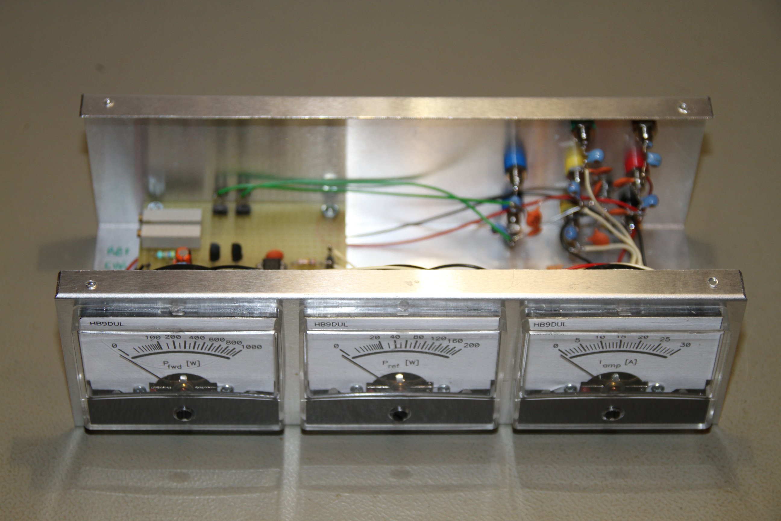
Meter unit, front view (click to enlarge).
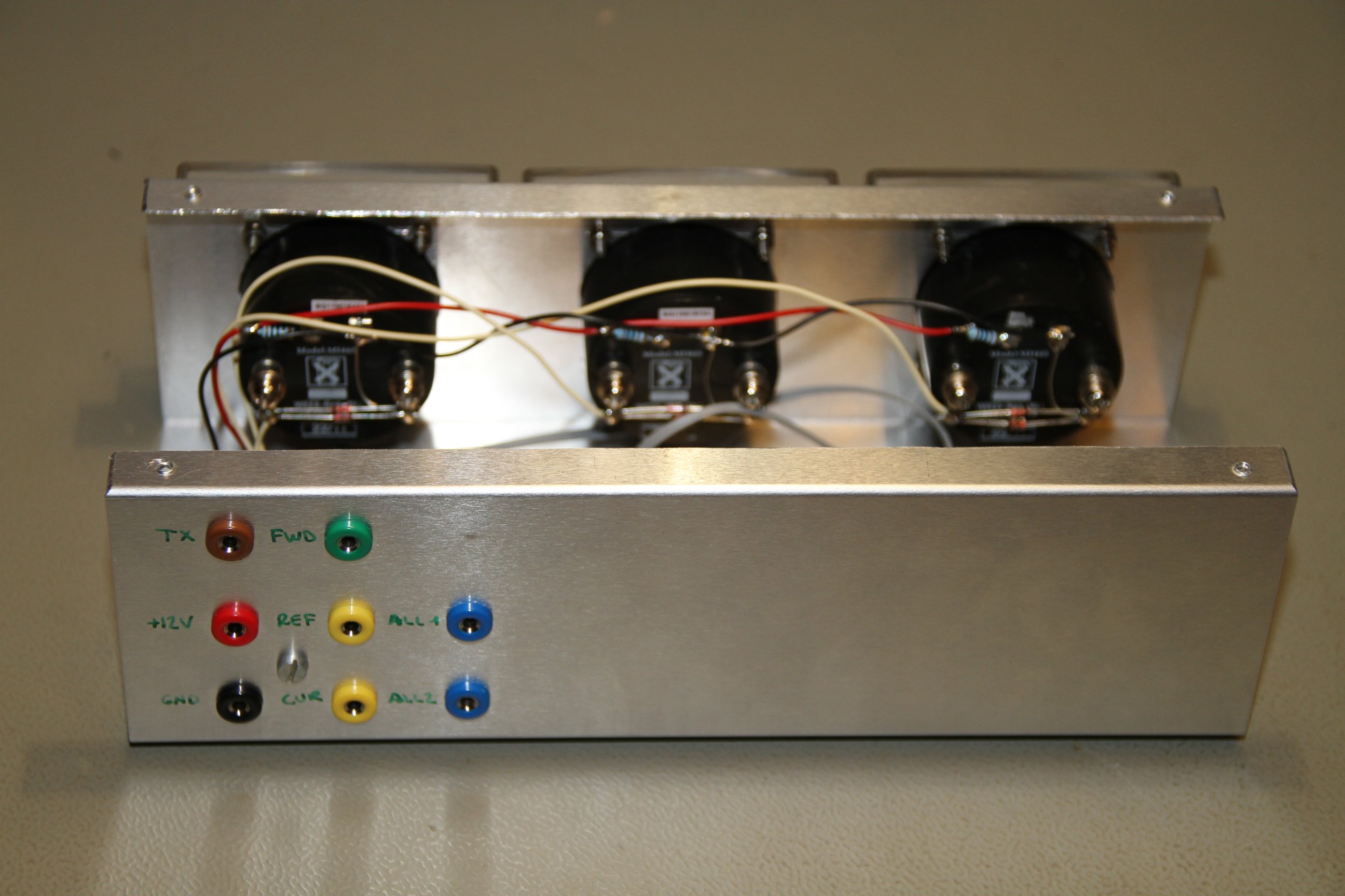
Meter unit, back view (click to enlarge).
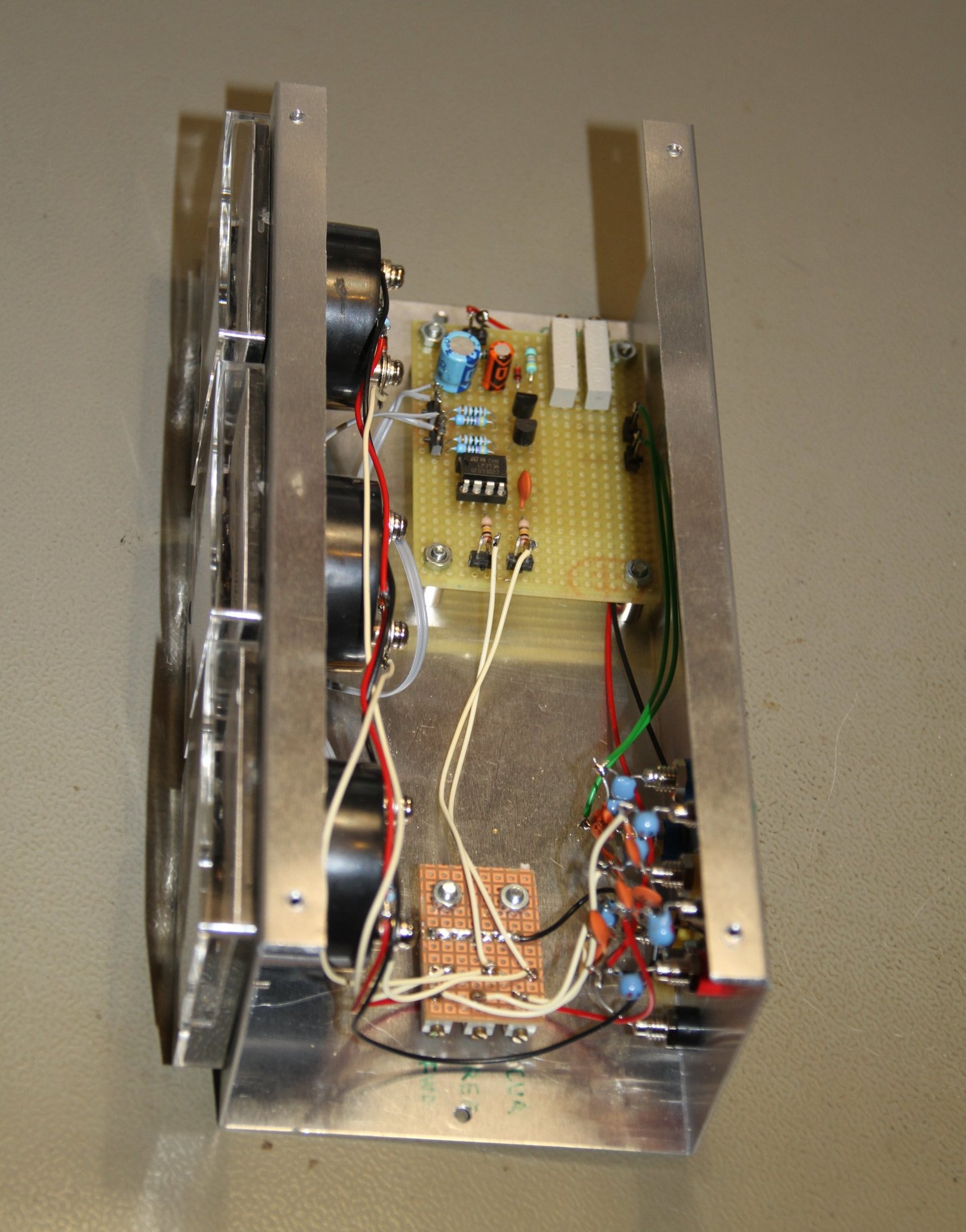
Meter unit, right view (click to enlarge).
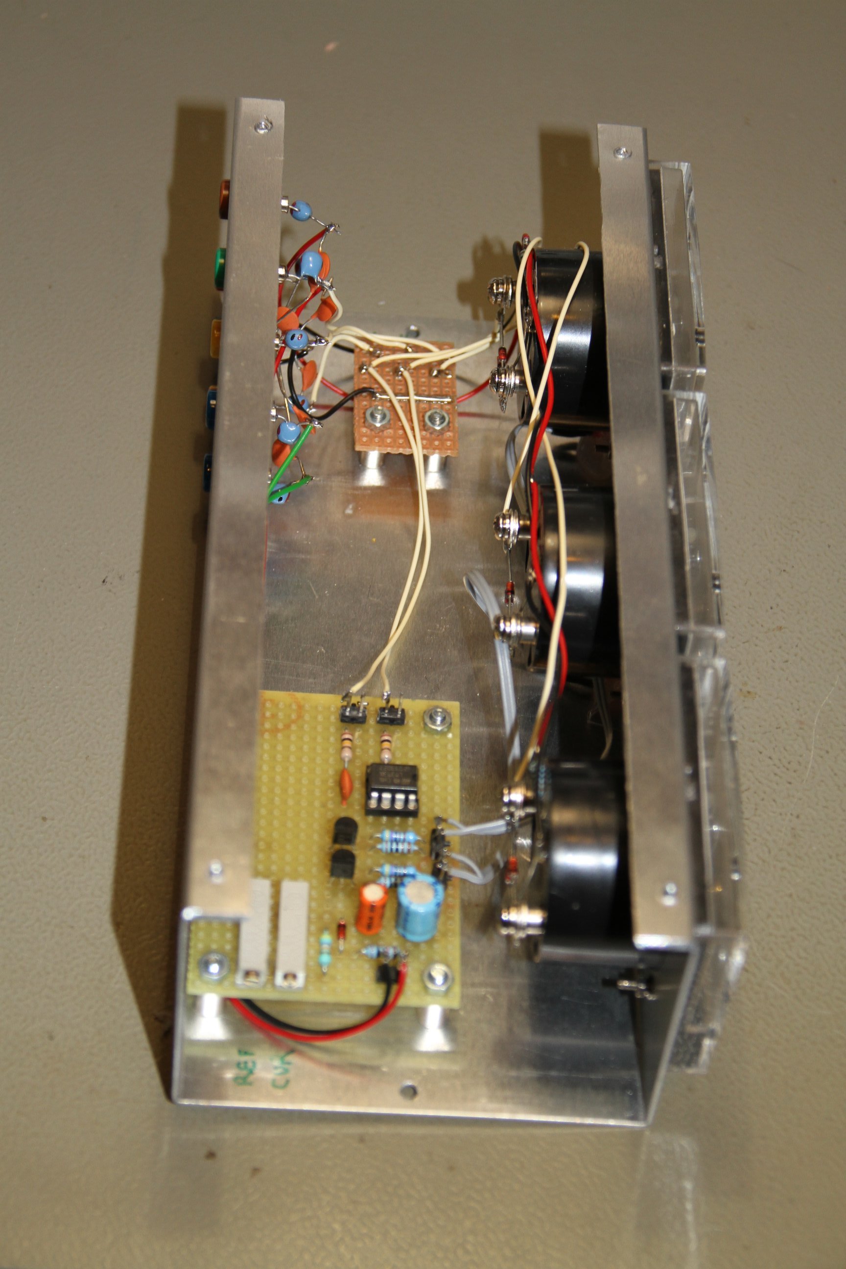
Meter unit, left view (click to enlarge).
| Home | Electronics | Index | Previous page | Next page |