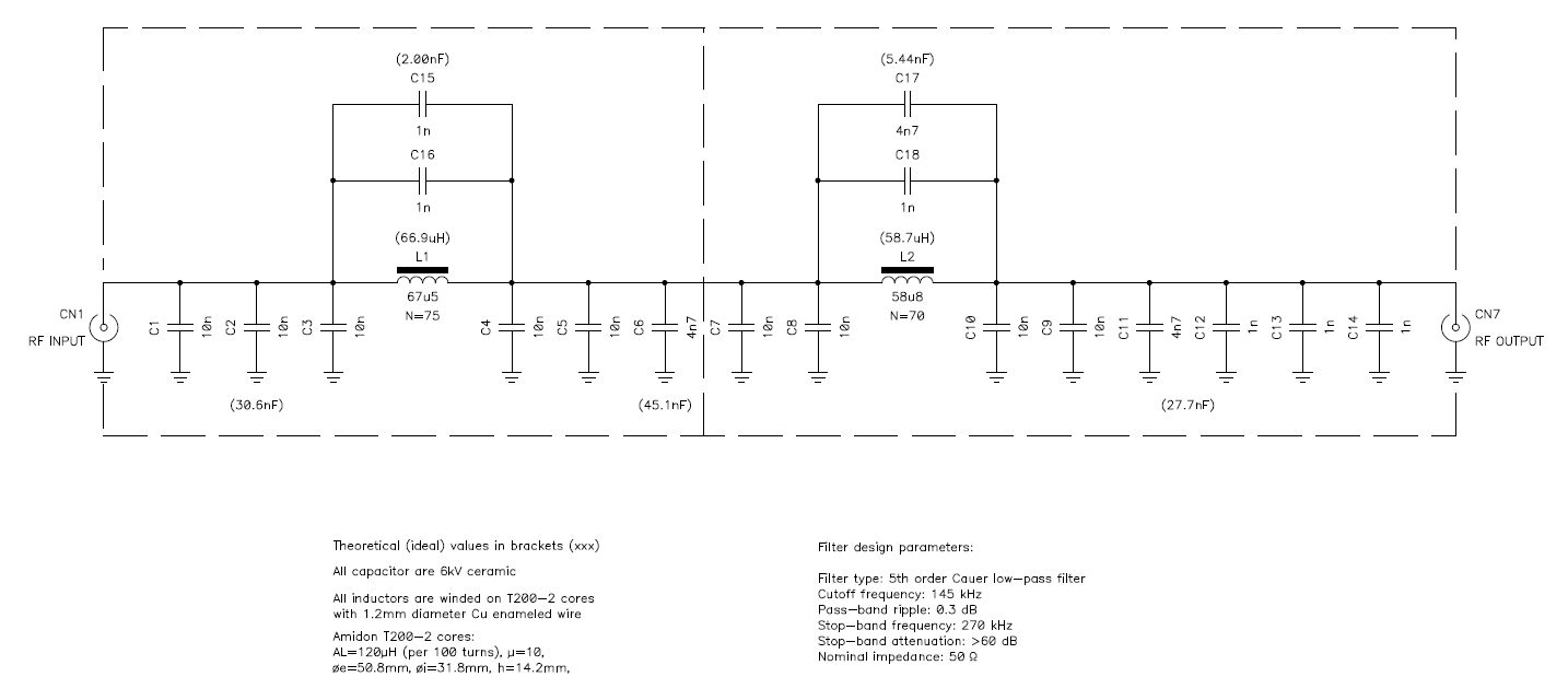
Circuit diagram of the LW filter unit (click to enlarge). – A PDF version is also available: filtercircuit.lw.pdf (31,176 bytes).
The final unit generates a square signal. In order to meet regulations, this signal must be filtered in order to remove the high harmonic content and let only a nice sine wave reach the antenna. Since the two frequencies are too far apart, it's not possible to accommodate both 137 and 500 kHz bands with just one filter, and two different filters must be used.
It's not easy to just switch between two filters with just a simple double-pole double-throw switch, because stray coupling can ruin the whole filter response. Of course, it's possible to switch with two relays and a lot of shielding, but this solution looked too complicated. Finally, to keep things simple, both filter units have BNC connectors and can easily be swapped just by moving two jumper cables: it's simple, reliable and provides the best shielding.
When designing a filter, the first choice to make is to choose a filter configuration, like Bessel, Butterworth, Cauer,... There is no perfect filter and every configuration has pros and cons. For this transmitter the Cauer configuration has been selected because it gives by far the steeper slope between pass-band and stop-band. The price to pay for such a response is a non-linear phase response that doesn't really matters for a CW transmitter, a relatively high return loss in the pass-band which is not an issue for our MOSFET final unit and, of course, an additional capacitor in parallel with each inductor.
The following parameters were used for the design of the filter:
| Configuration: | Cauer low-pass |
| Filter order: | 5th order |
| Cutoff frequency: | 145 kHz |
| Pass-band ripple: | 0.3 dB |
| Stop-band frequency: | 270 kHz |
| Stop-band depth: | 60 dB |
| Impedance: | 50 Ω |
The design gives, of course, non standard values for inductors and capacitors and approximations are required. Theoretical values are reported in brackets on the schematic diagram. The inductors are manually winded to the right value and several capacitors in parallel are used to match the desired value.
Circuit diagram of the LW filter unit (click to enlarge). –
A PDF version is also available: filtercircuit.lw.pdf (31,176 bytes).
For the inductors, a low permeability core is required in order to wind enough turns to closely match the desired inductance value. If a too high permeability core is used (like a ferrite core), just adding or removing one turn results in a too big inductance change and the desired exact value will be missed. Amidon T200-2 powdered-iron toroidal cores were selected because of their low permeability (μ=10 and AL = 120 μH for 100 turns). This core is fairly big (external diameter: 50.8 mm, internal diameter 31.8 mm and height: 14.2 mm) and allows using a thick wire (such as a 1.2 mm diameter enameled wire) that is required for the desired power.
The voltage across the capacitors can be higher than expected because of the high Q factor of the resonant circuits, therefore high voltage ceramic capacitors are mandatory for this application.
In order to achieve a good filter response, it's important to reduce stray coupling between the elements of the filter. A shield between the two Π cells is a good idea: it breaks the capacitive coupling between input and output and prevents any inductive coupling between the two inductors.
Even if the components have all a different value, the filter is symmetrical: input and output can be swapped without any change in the performance.
The measured transfer function is shown in the graph below. The response is close but doesn't completely match design specifications, mainly because of the tolerances in the values of the components. In any case, such a filter is perfectly suitable for this transmitter and the harmonic suppression will easely meet regulations.
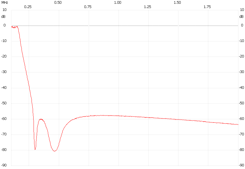
Frequency response of the LW filter.
The following two pictures show how the filter has been built. During full power operation some heat is generated in the coils and a few holes to allow proper ventilation should be included in the case.
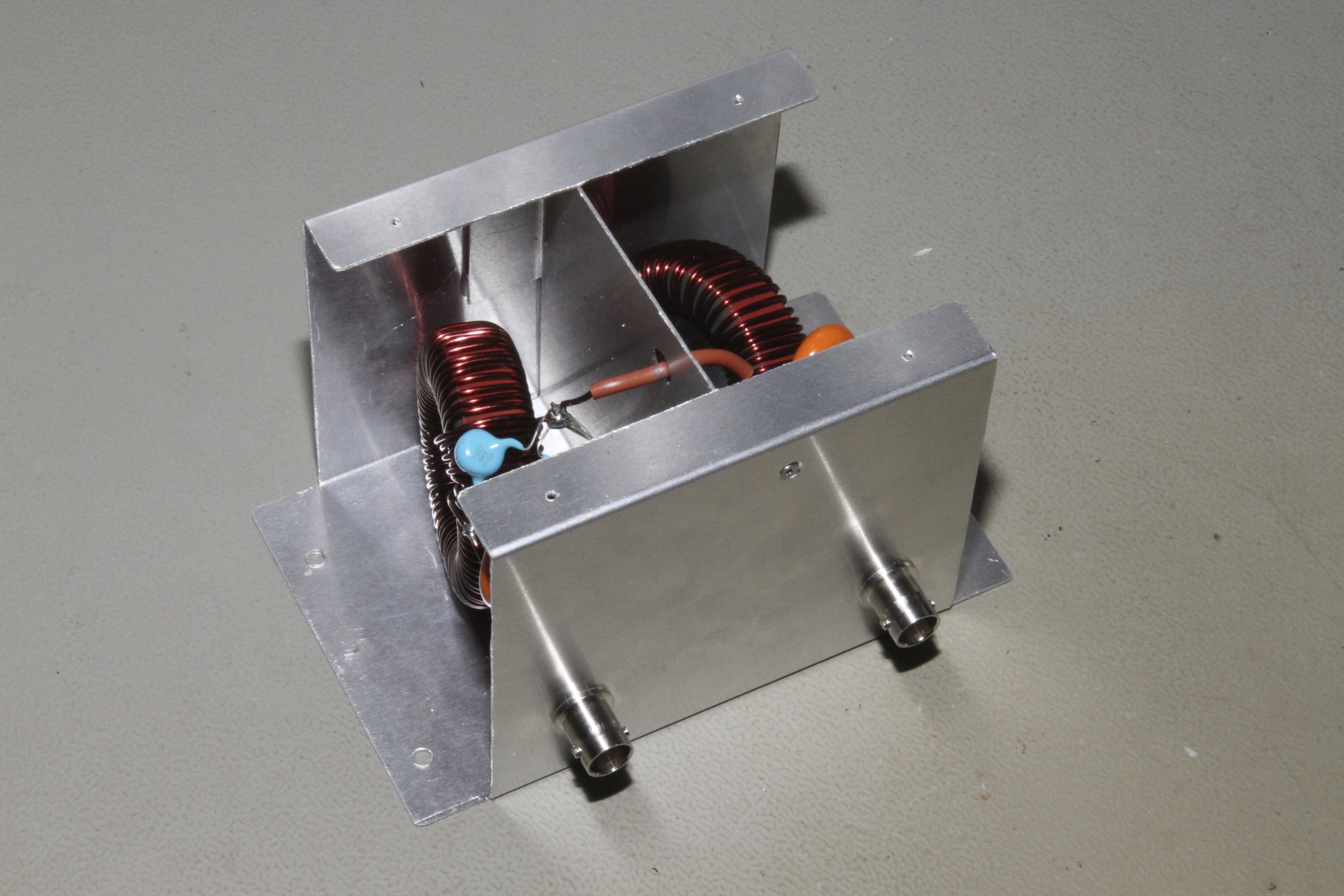
Long-waves filter unit, front view (click to enlarge).
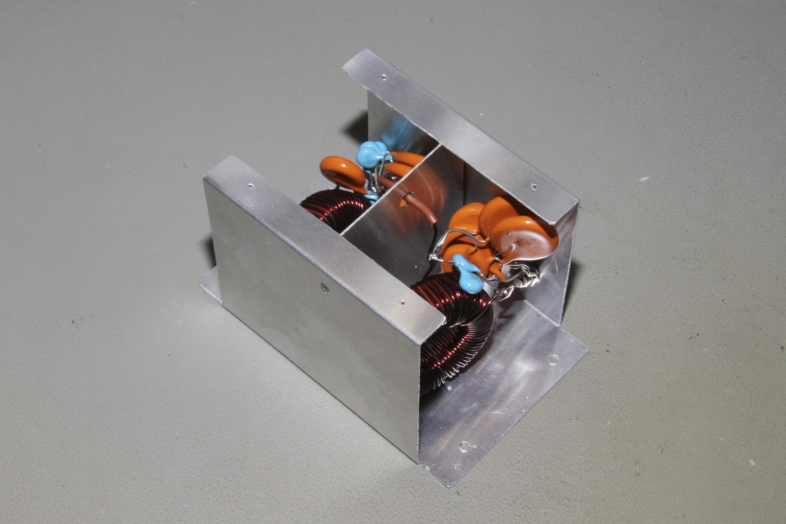
Long-waves filter unit, back view (click to enlarge).
The 500 kHz filter is identical in design and very similar in construction. When this filter has been designed the 500 kHz band was not (yet, maybe) allowed for amateur use. There were rumors saying that this band will probably be below 500 kHz, maybe somewhere between 472 and 479 kHz, therefore the design parameters for this filter have been selected as follows:
| Configuration: | Cauer low-pass |
| Filter order: | 5th order |
| Cutoff frequency: | 490 kHz |
| Pass-band ripple: | 0.1 dB |
| Stop-band frequency: | 1 MHz |
| Stop-band depth: | 60 dB |
| Impedance: | 50 Ω |
If, one day, this band will be assigned for amateur use in Switzerland, and if the frequency will be slightly different from what was originally assumed, retuning this filter by slightly scaling all its component values won't be a big deal.
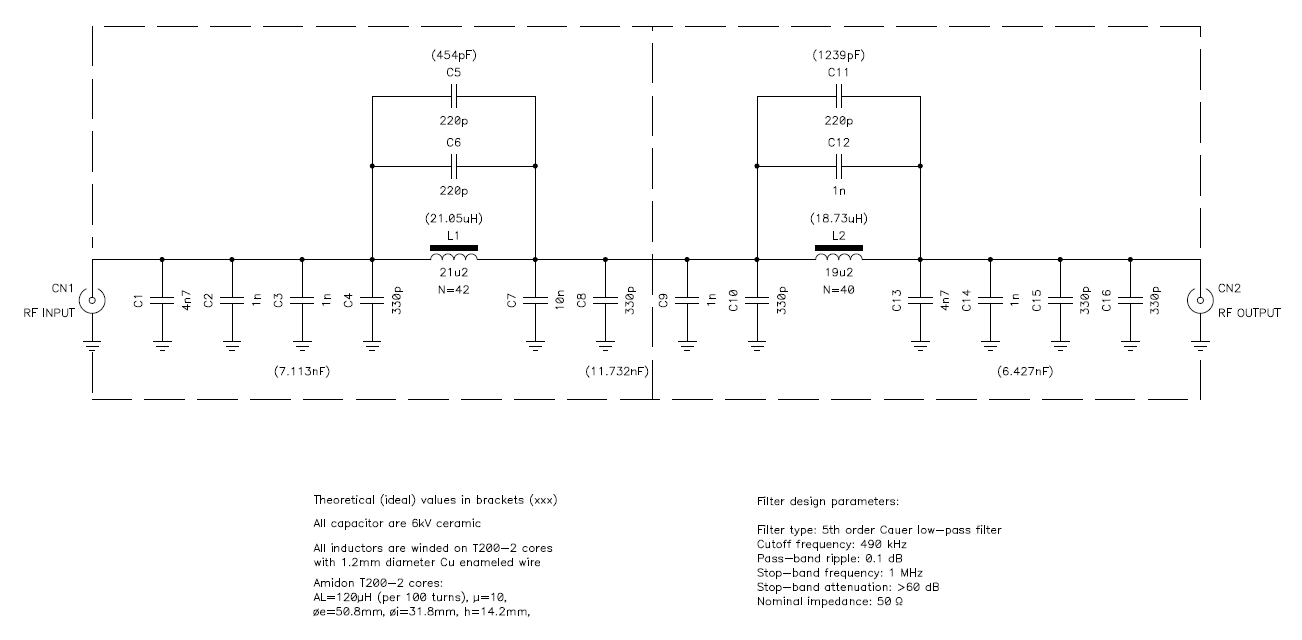
Circuit diagram of the MW filter unit (click to enlarge). –
A PDF version is also available: filtercircuit.mw.pdf (30,925 bytes).
The measured response of this filter is visible in the figure below. It's a bit worse than expected, but definitively acceptable for this application.
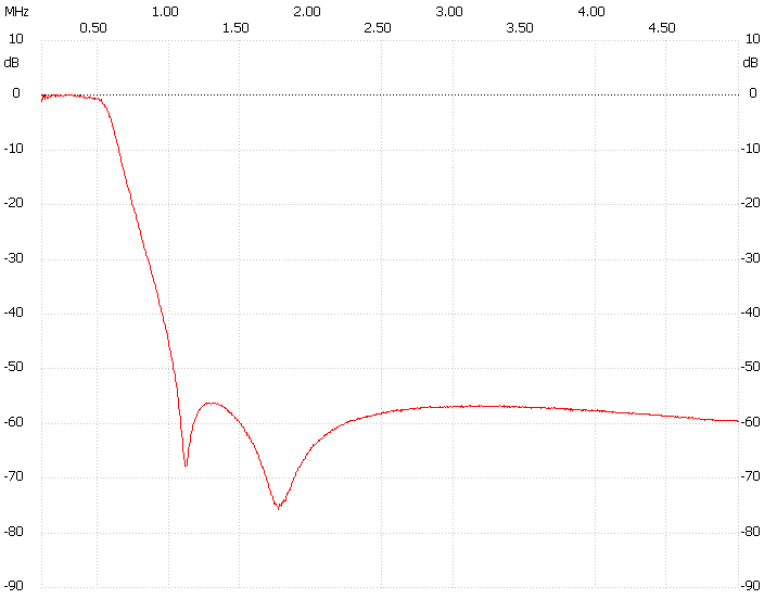
Frequency response of the MW filter.
The same considerations as before also apply to this filter which it very similar to the previous one, as one can see in the following pictures.
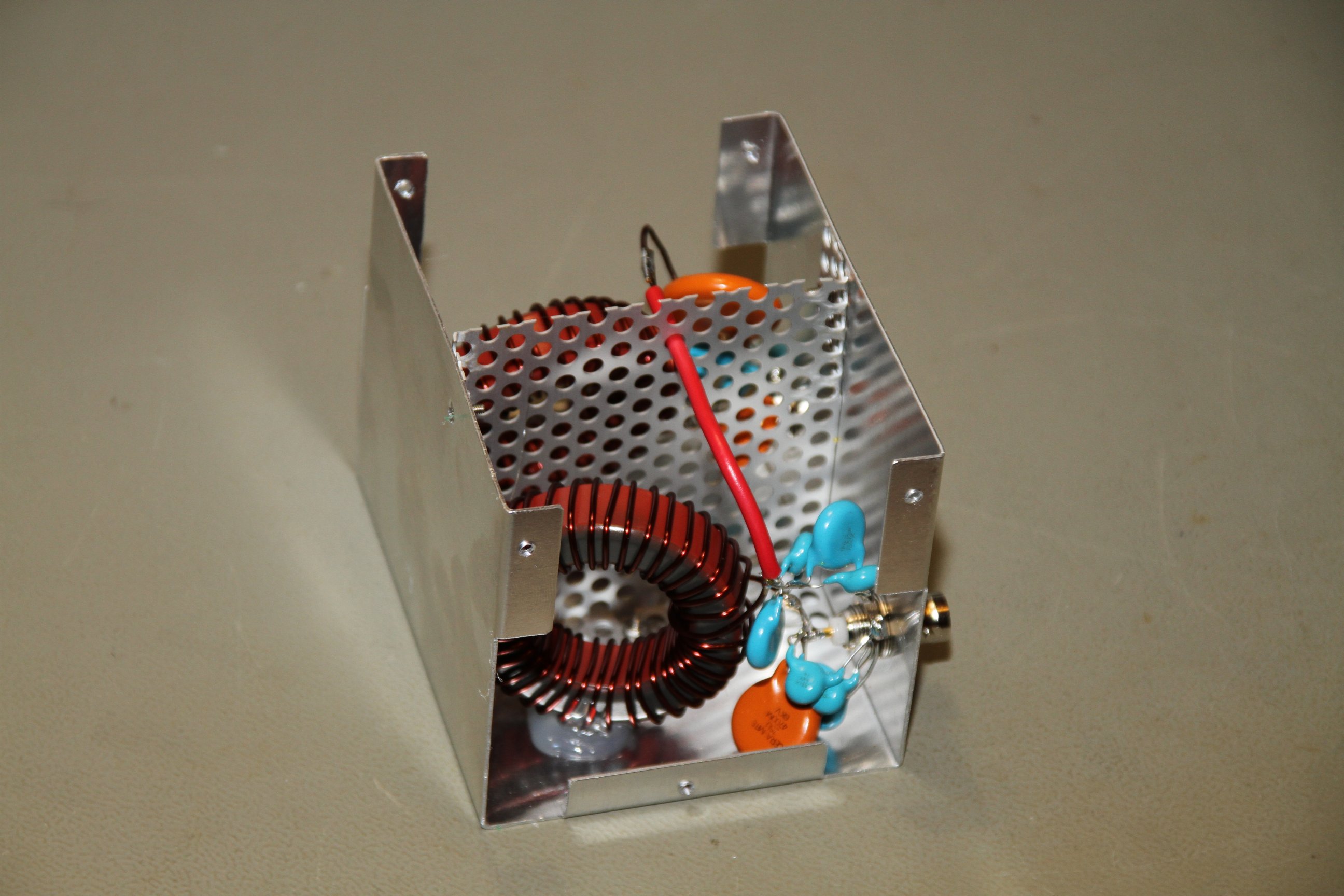
Medium-waves filter unit, left view (click to enlarge).
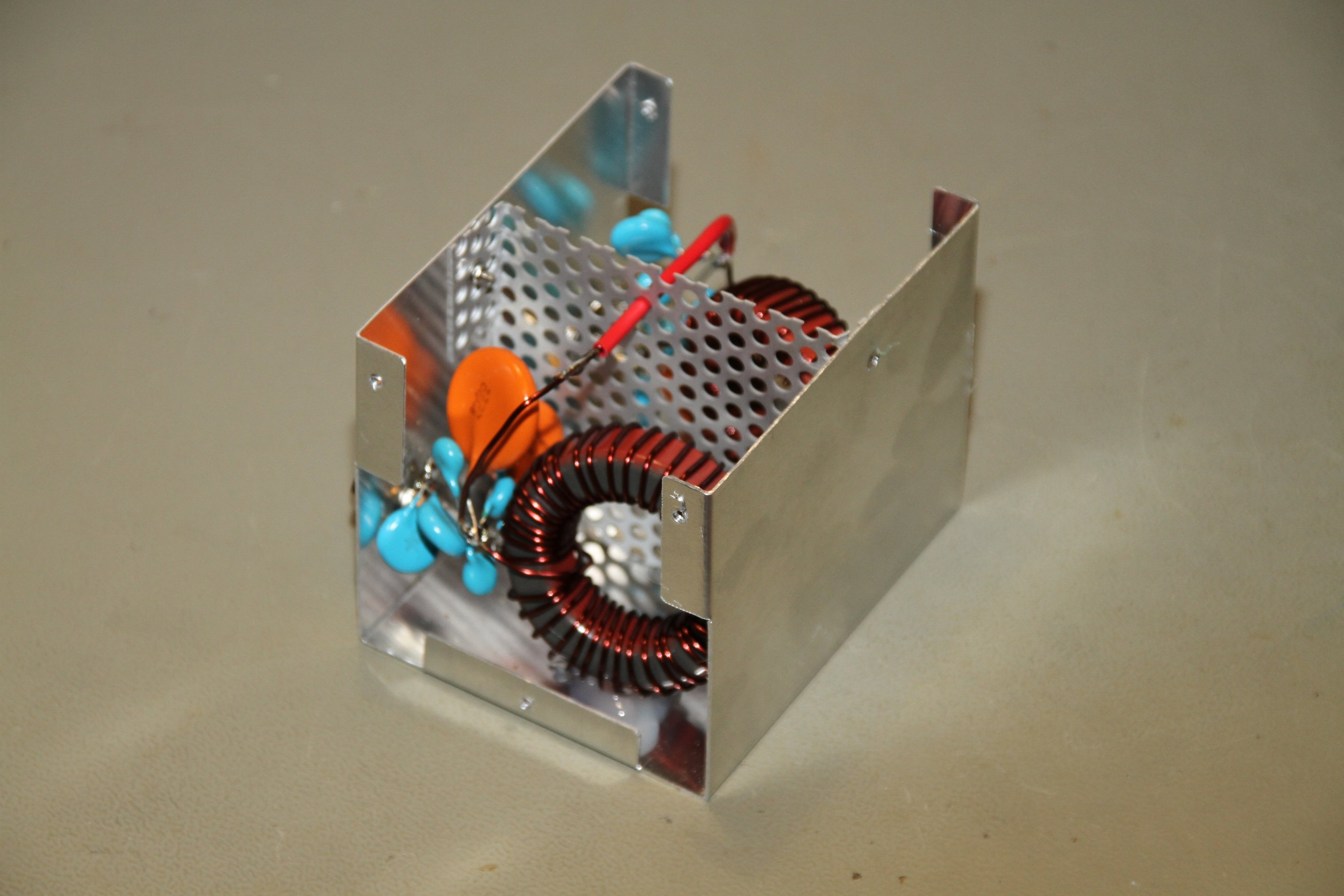
Medium-waves filter unit, right view (click to enlarge).
| Home | Electronics | Index | Previous page | Next page |