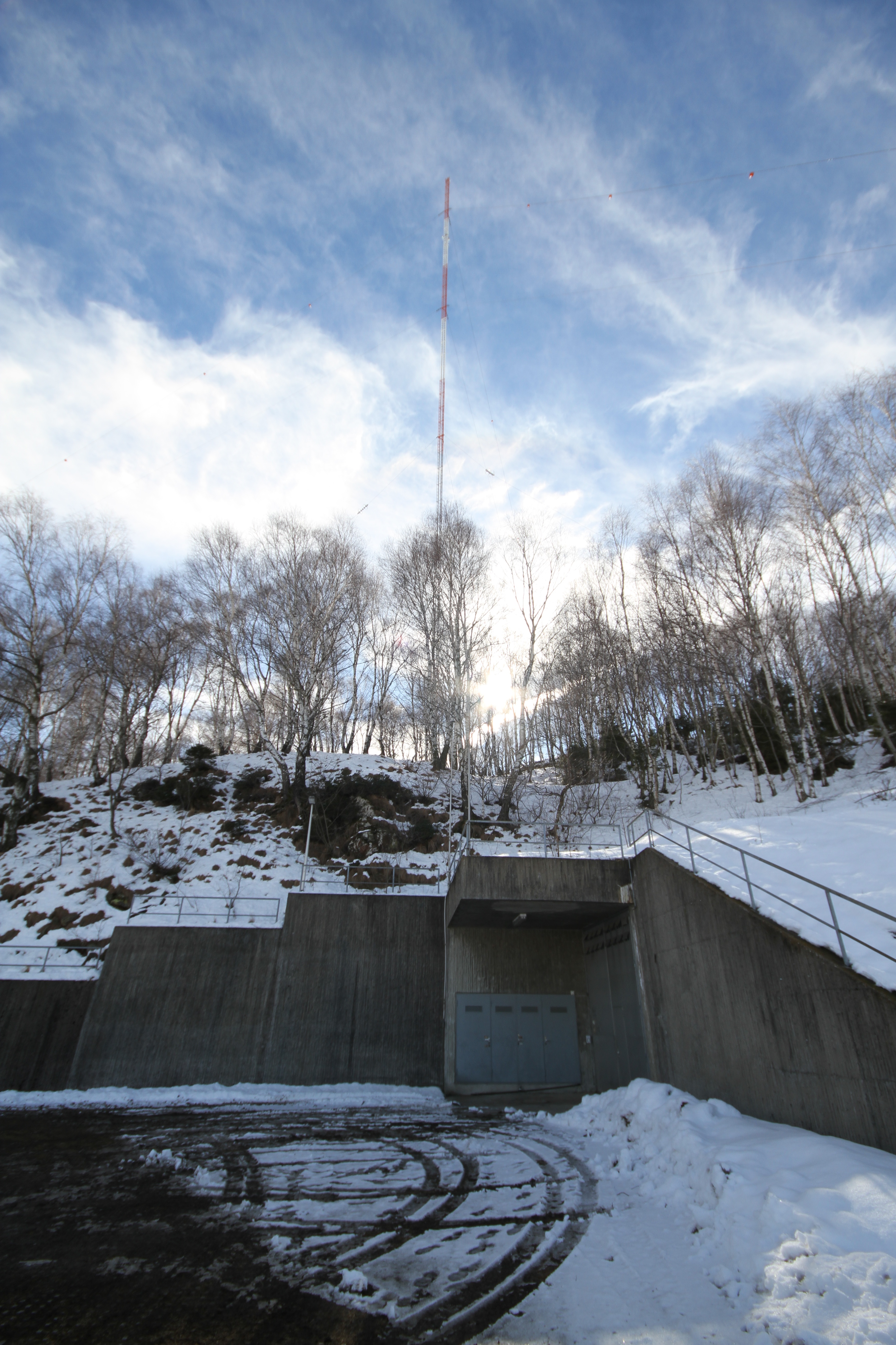
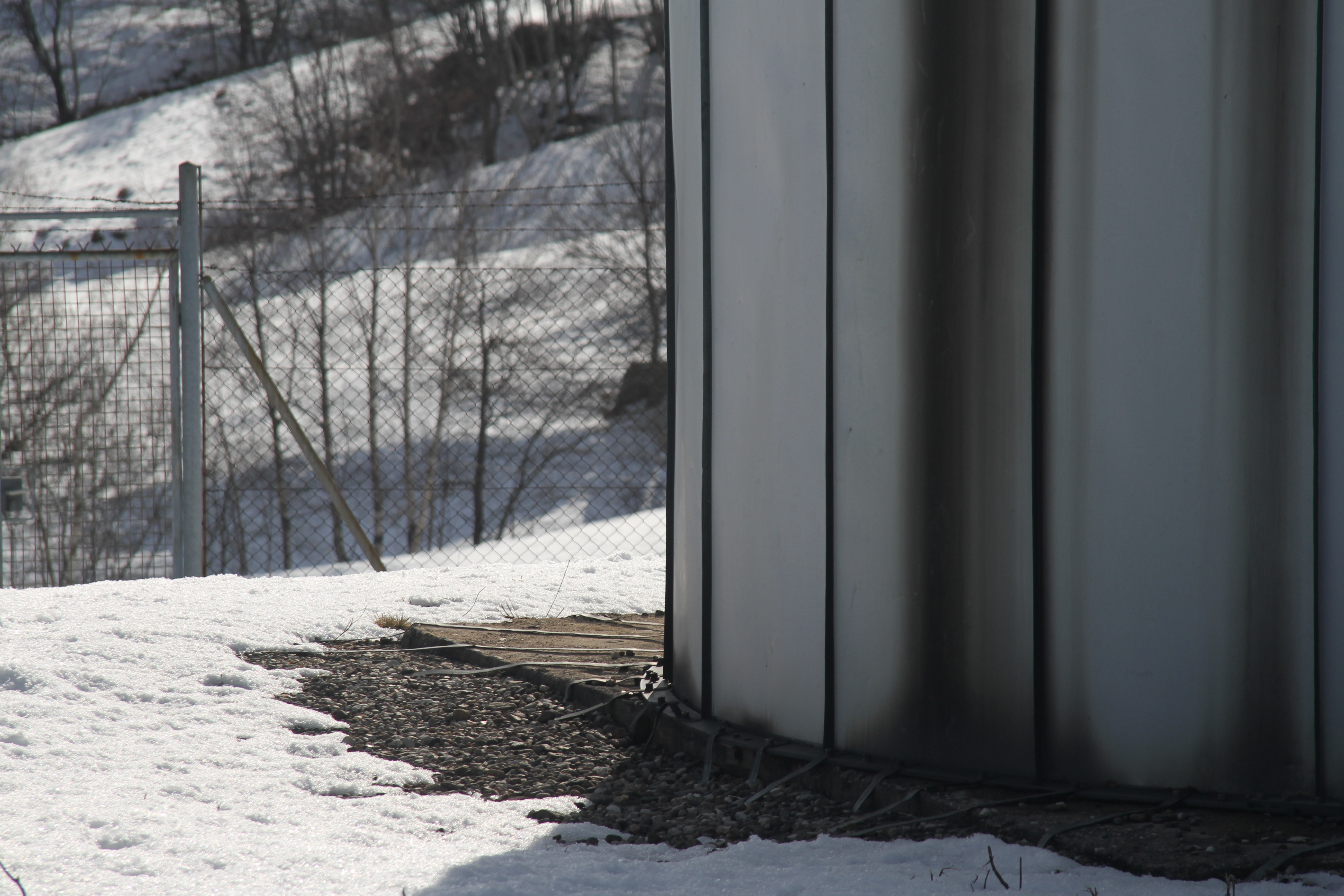
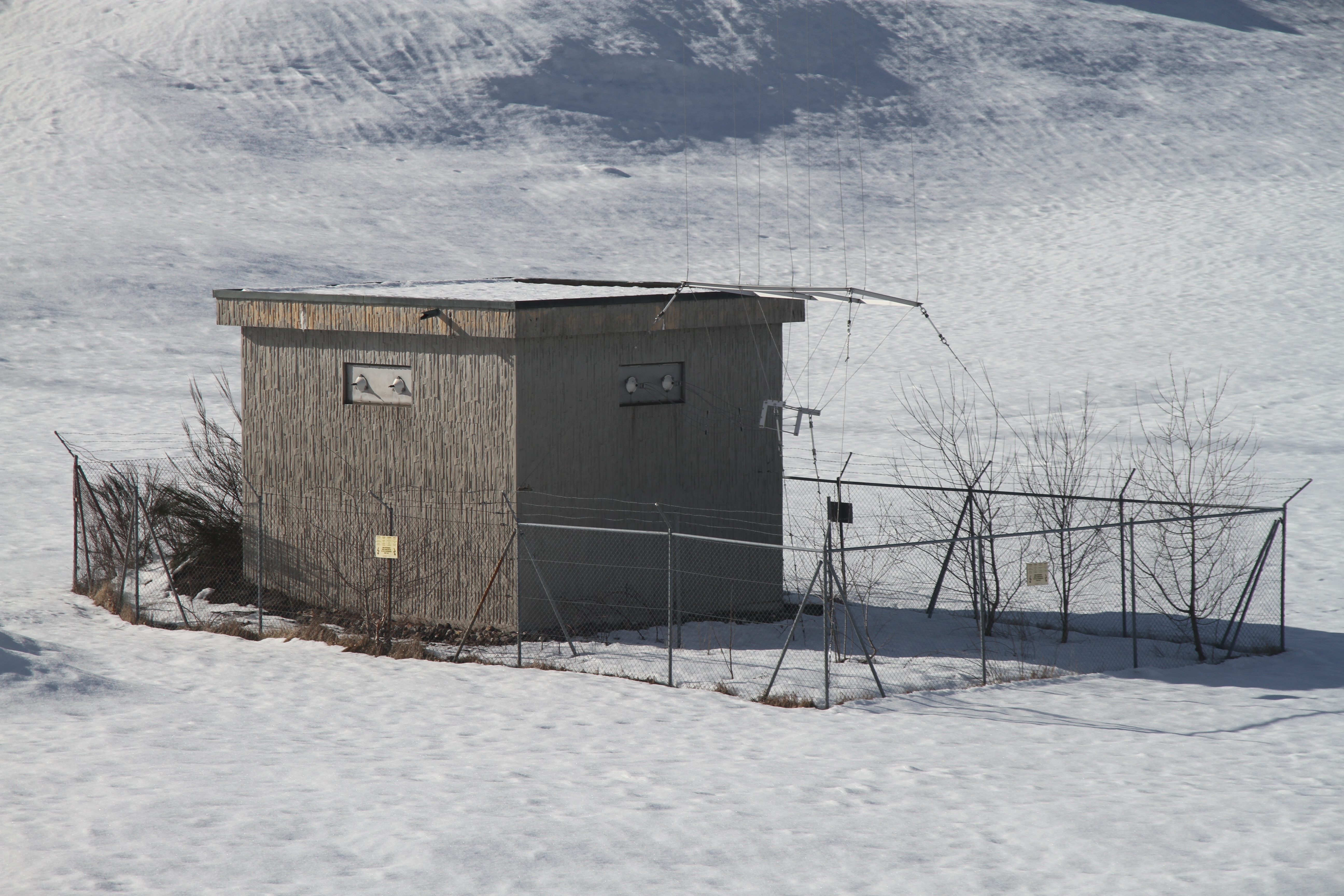
Underground transmitter building.

Transmitter building entrance.
| Location: | E 8° 59' 25.51" / N 46° 08' 19.16" |
| Frequency: | Transmitter is off (used to be 558 kHz). |
| Wavelength: | Transmitter is off (used to be 538 m). |
| Power: | Transmitter is off (used to be 300 kW). |
| Call-sign: | Used to be "Radio Monte Ceneri", then "Radio Svizzera, Rete Uno" (and temporarely "La voce della Russia"). |
| Transmission type: | Medium wave AM broadcast station. |
The transmitter was switched off in December 2012 and both antennas (main and spare) have been dismantled in July 2016.
The Monte Ceneri radio station started operating on April 18, 1933 with a 15 kW Marconi transmitter on 650 m (461 kHz) from the Monte Ceneeri Pass location. In 1934 the frequency was changed to 1167 kHz (257 m). In 1951 the power is increased to 50 kW and the frequency changed to 557 kHz (539 m) according to the Copenhagen plan. In 1967 the power is further increased to 100 kW. At the end of 1978 the frequency is changed to 558 kHz (538 m) to follow the plan of Geneva. In October 1979 the transmitter moved to the Monte Ceneri Cima location (about 6 km to the East) with a new antenna and a new 300 kW transmitter. This station was initially named "Radio Monte Ceneri" and later changed to "Radio Svizzera, Rete Uno". The transmitter was switched off in June 2008. It started transmitting again in January 2011 to broadcast the "Voice of Russia" for a few hours every day and was switched off again in December 2012. Both antennas (main and spare) have been dismantled in July 2016. The transmitter building is still there.
Underground transmitter building. |
Transmitter building entrance. |
| Tower type: | 220 m guyed tower. |
| Antenna type: | 0.4λ (144°) vertical tower, isolated from ground. |
| Feed point: | Base of the tower. |
| Ground plane: | 120 buried radials, 200 m long. |
This antenna was built in 1978 and switched on in 1979, replacing the old Monte Ceneri Pass tower (about 6 km West). This antenna was dismantled in July 2016.
When the transmitter is operating one can clearly hear the modulation by standing near where the internal (short) guy wires ere connected to ground. The antenna simulation shows that a very high current is present at this point.
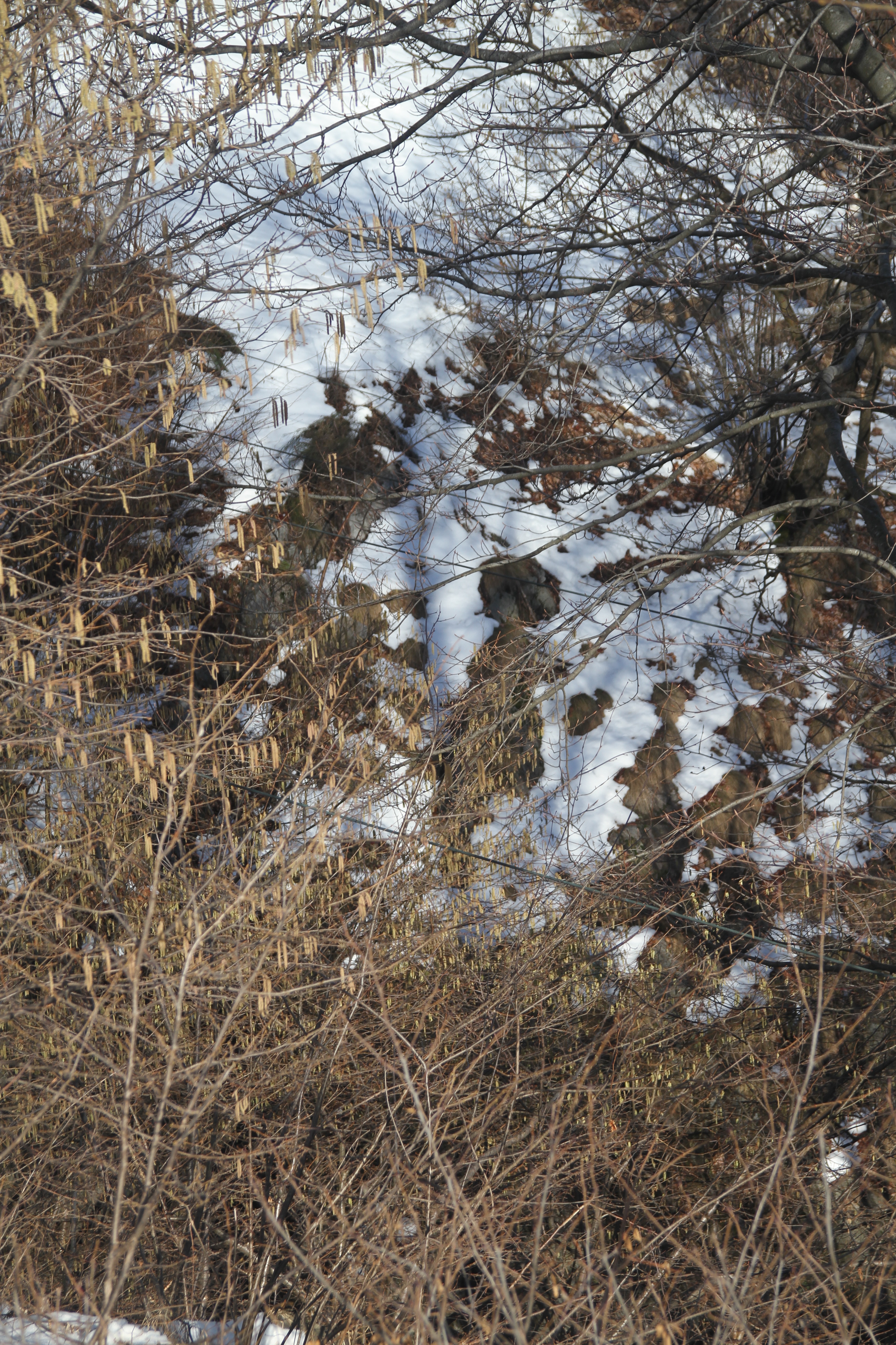
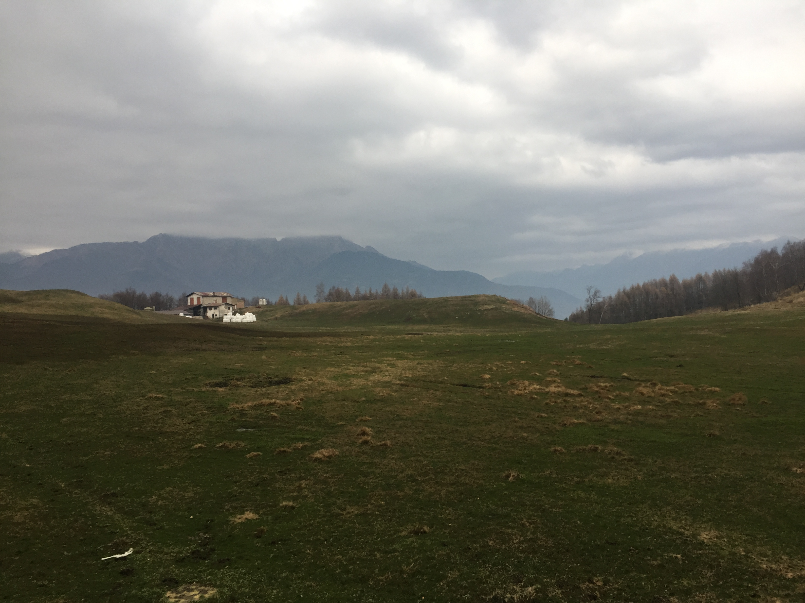
Today this antenna has been dismantled and only little evidence remains of the old structure.
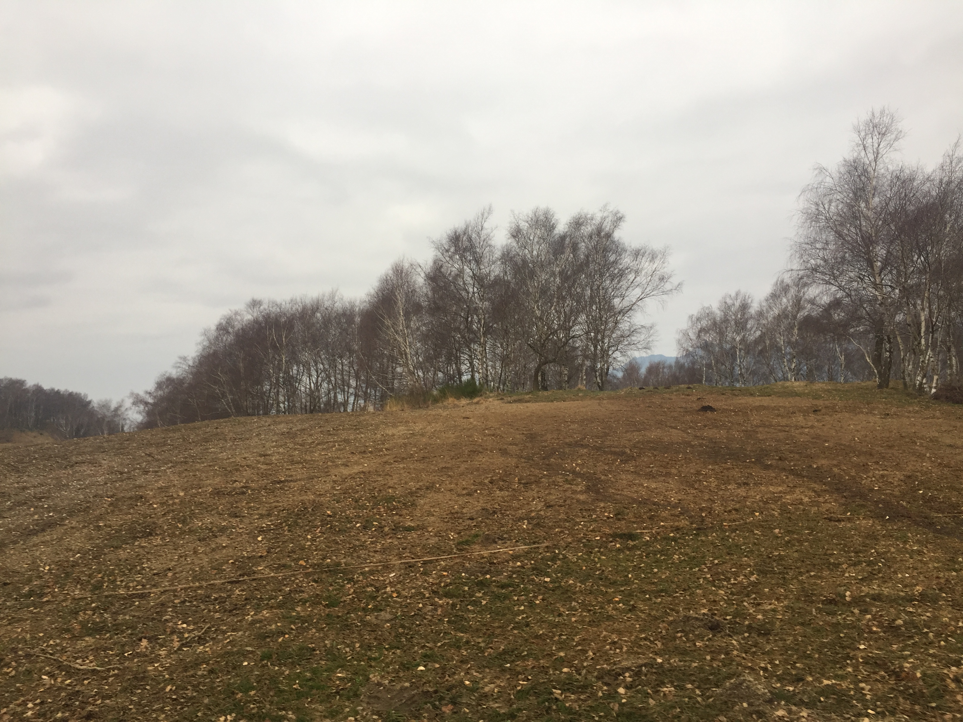 This is where the main antenna was standing. The original aspect of land has been reestablished and no visible sign of the structure remains. (Dec. 2016) |
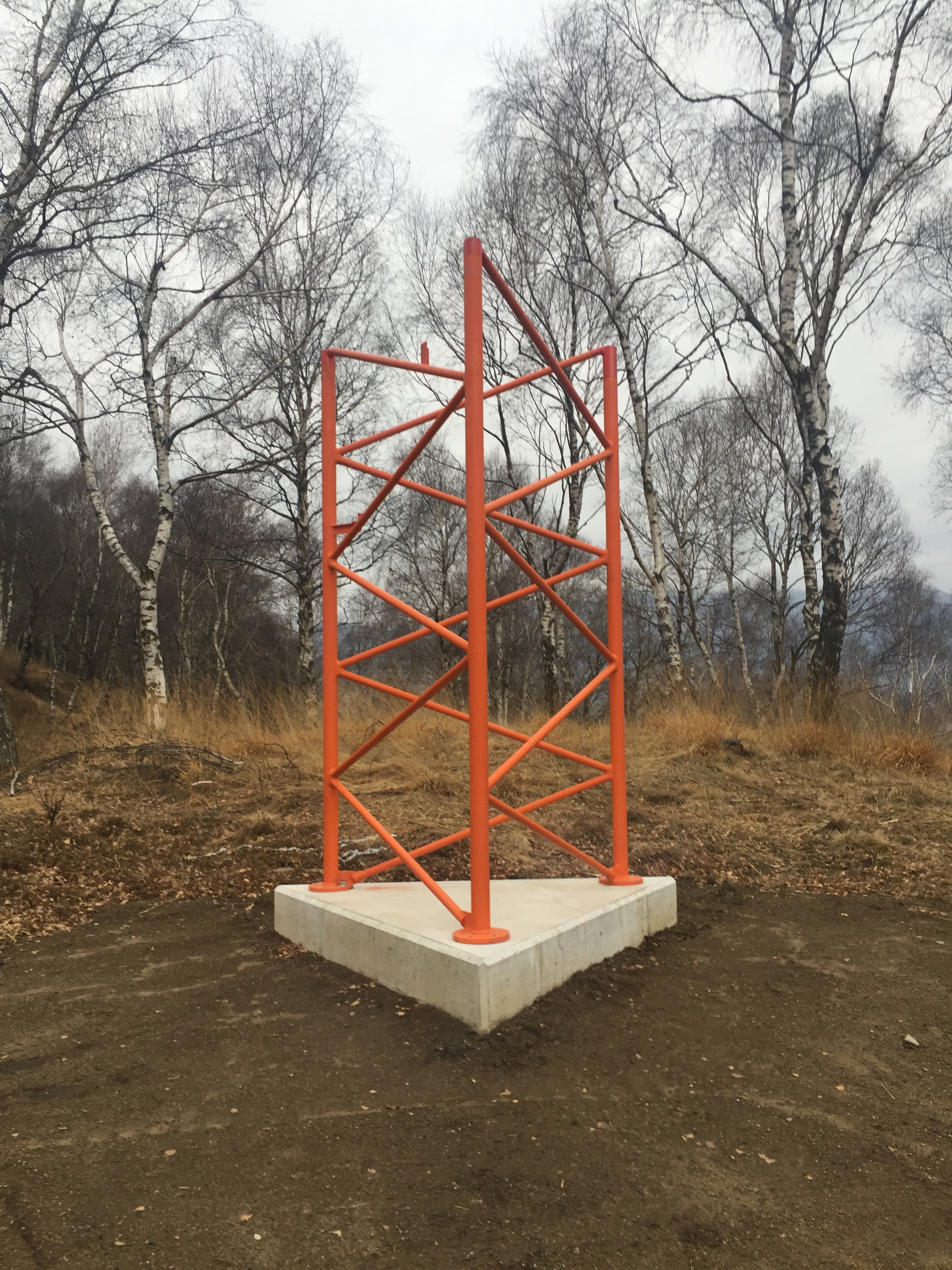 This short section of the old mast is located on the side of the street to the transmitter building, a sort of monument for this structure. (Dec. 2016) |
 There is very little evidence left of the old ground system, only very little pieces of the copper straps remains on some rocks. (Dec. 2016) |
 Mainly only the "shadow" of the old ground system remains. No doubt that in a few years all signs will completely disappear. (Dec. 2016) |
The following pictures show how the antenna looked like in February 2011:
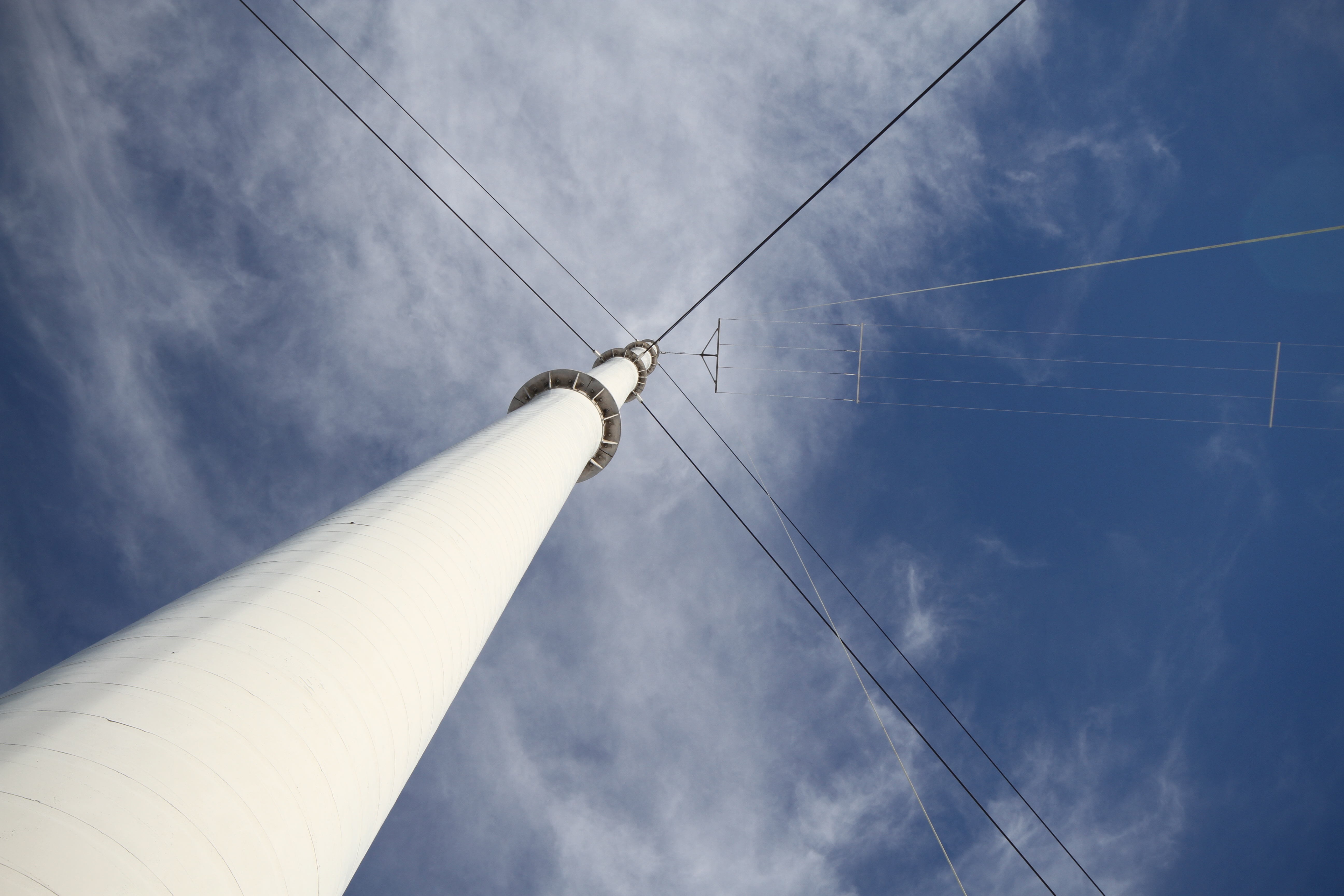
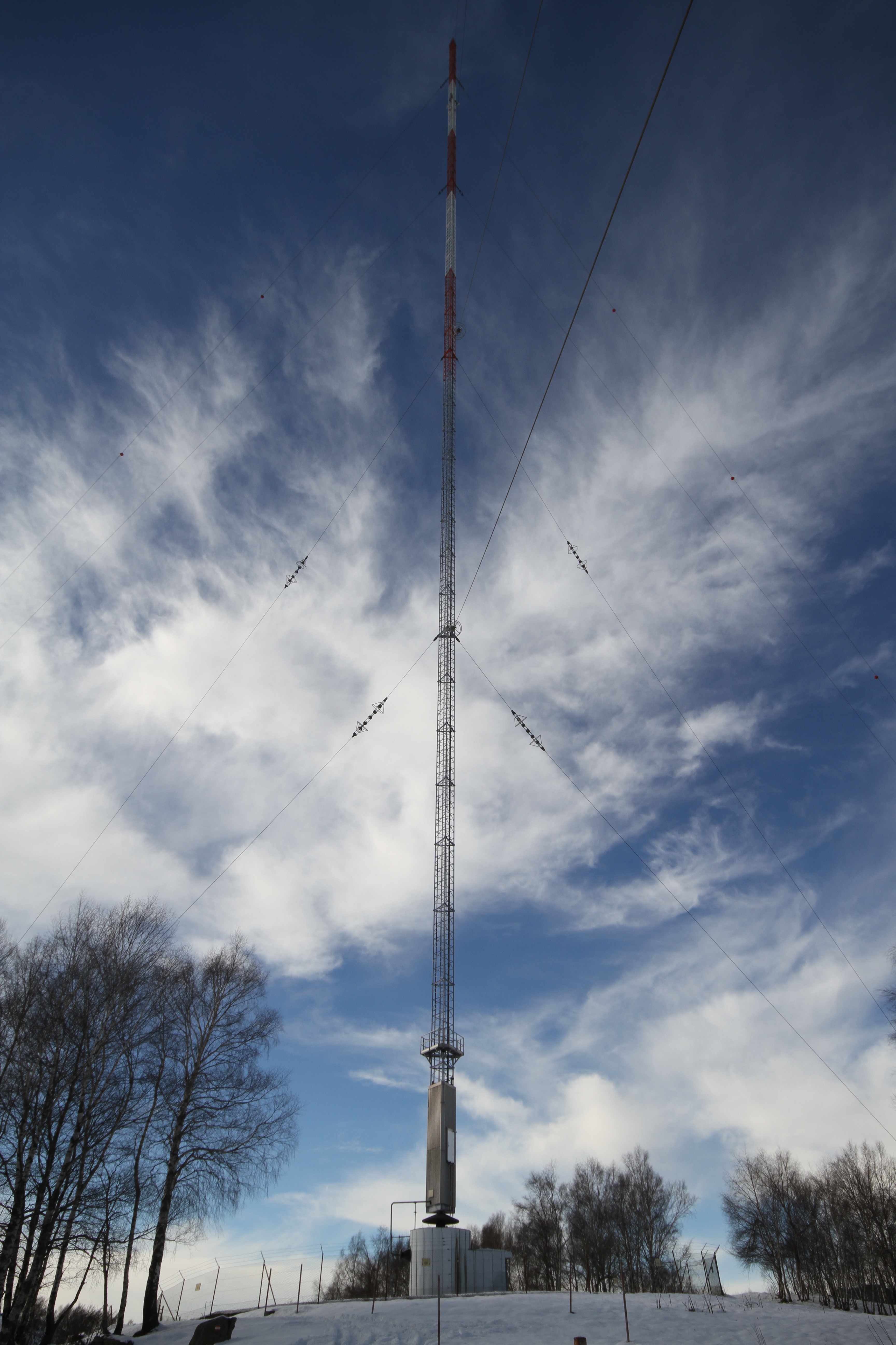 East view of the main antenna. (Feb. 2011) |
 South view of the main antenna. (Feb. 2011) |
 Main antenna match box and base insulator. (Feb. 2011) |
 Tower feed connection at its base. (Feb. 2011) |
 Long guy wires are directly grounded. Obstruction lights power connection and UV sensor on the background (red device on a pole). (Feb. 2011) |
 Short guy wires ground connection. (Feb. 2011) |
 Guy insulator close-up. (Feb. 2011) |
 Buried radials connected to the antenna match box at its base. (Feb. 2011) |
 Some buried radials are clearly visible. In spring, the snow melts faster on the radials. (Feb. 2011) |
 Suspended radials for crossing a small creek. (Feb. 2011) |
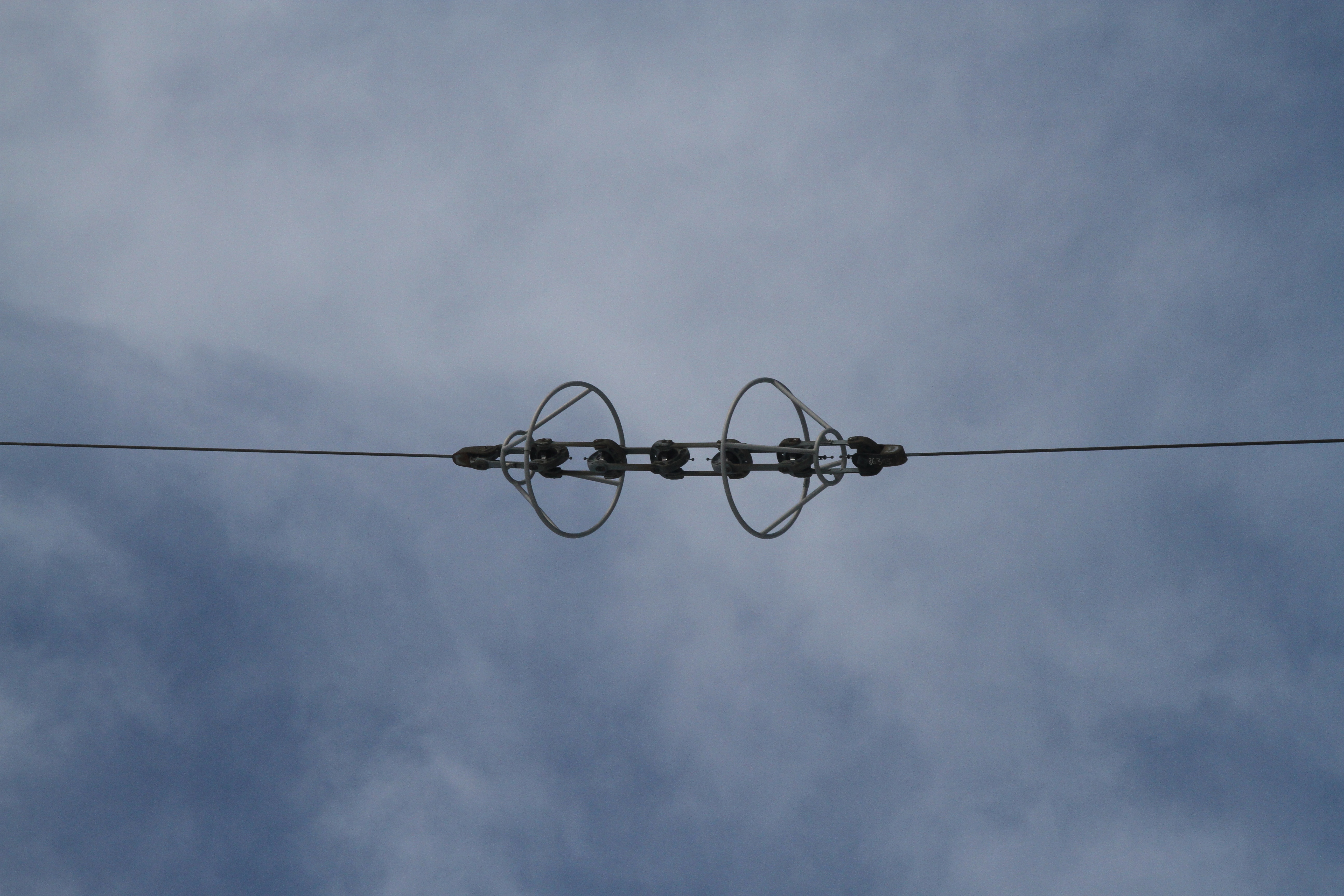
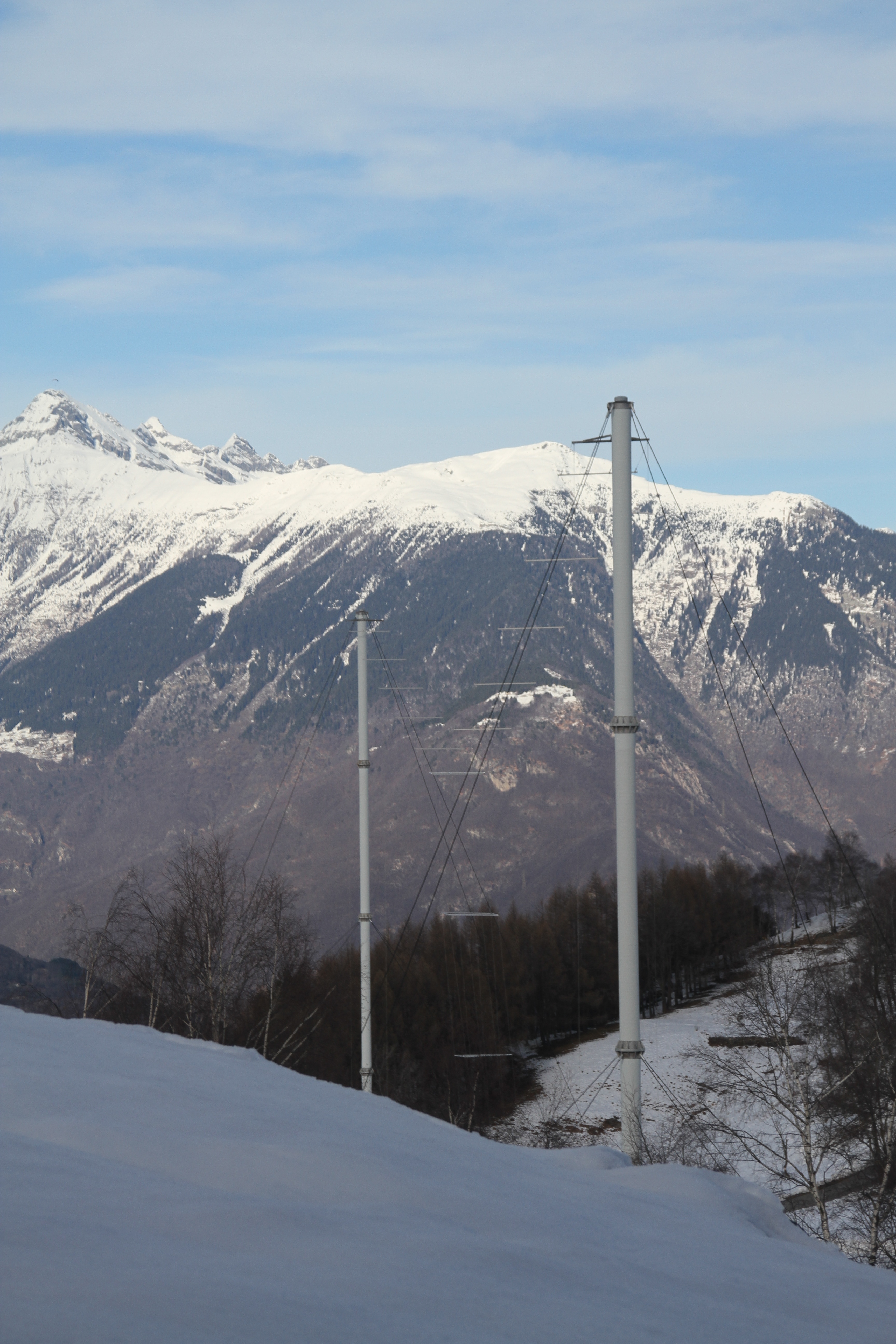
| Tower type: | Cage wires, suspended between two poles. |
| Antenna type: | Short vertical with huge capacitive hat, isolated from ground. |
| Feed point: | Base of the vertical cage. |
This antenna was dismantled in July 2016.
The following pictures show the location in December 2016 after the antenna has been removed.
 This is where the spare antenna was standing. (Dec. 2016) |
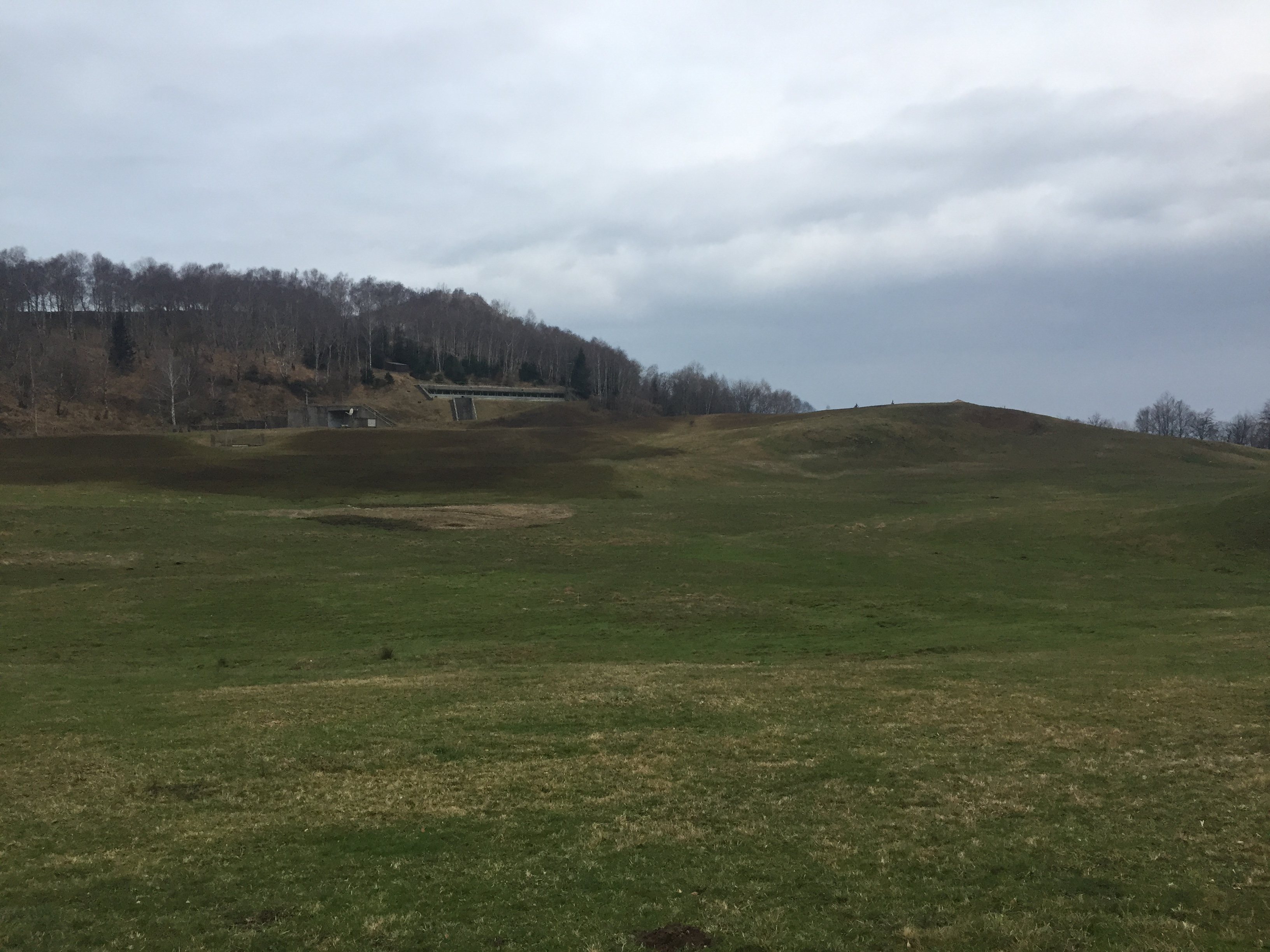 View of the location where the spare antenna was standing. On the background, the underground transmitter building is still visible. (Dec. 2016) |
This is how the antenna looked like in February 2011.
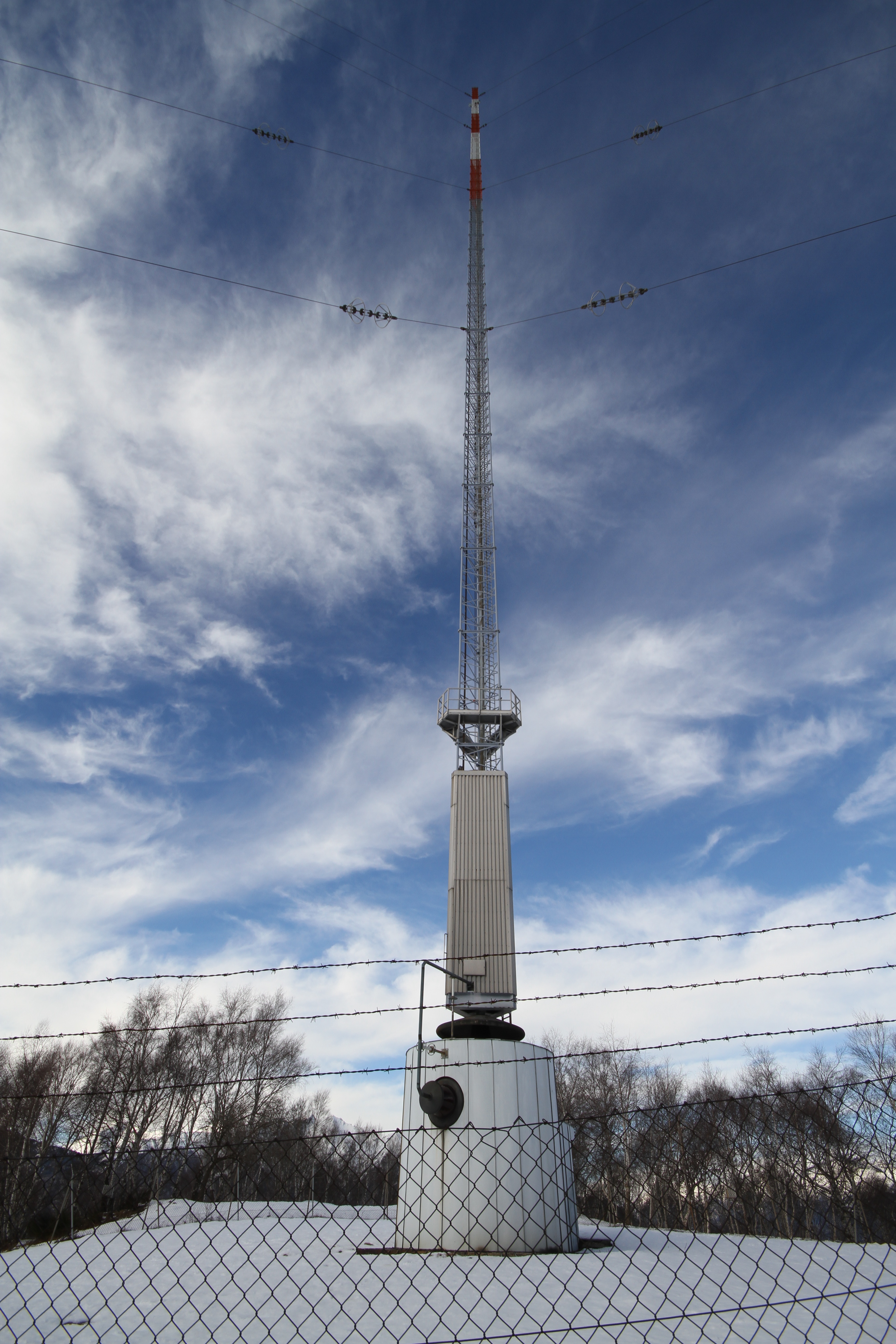
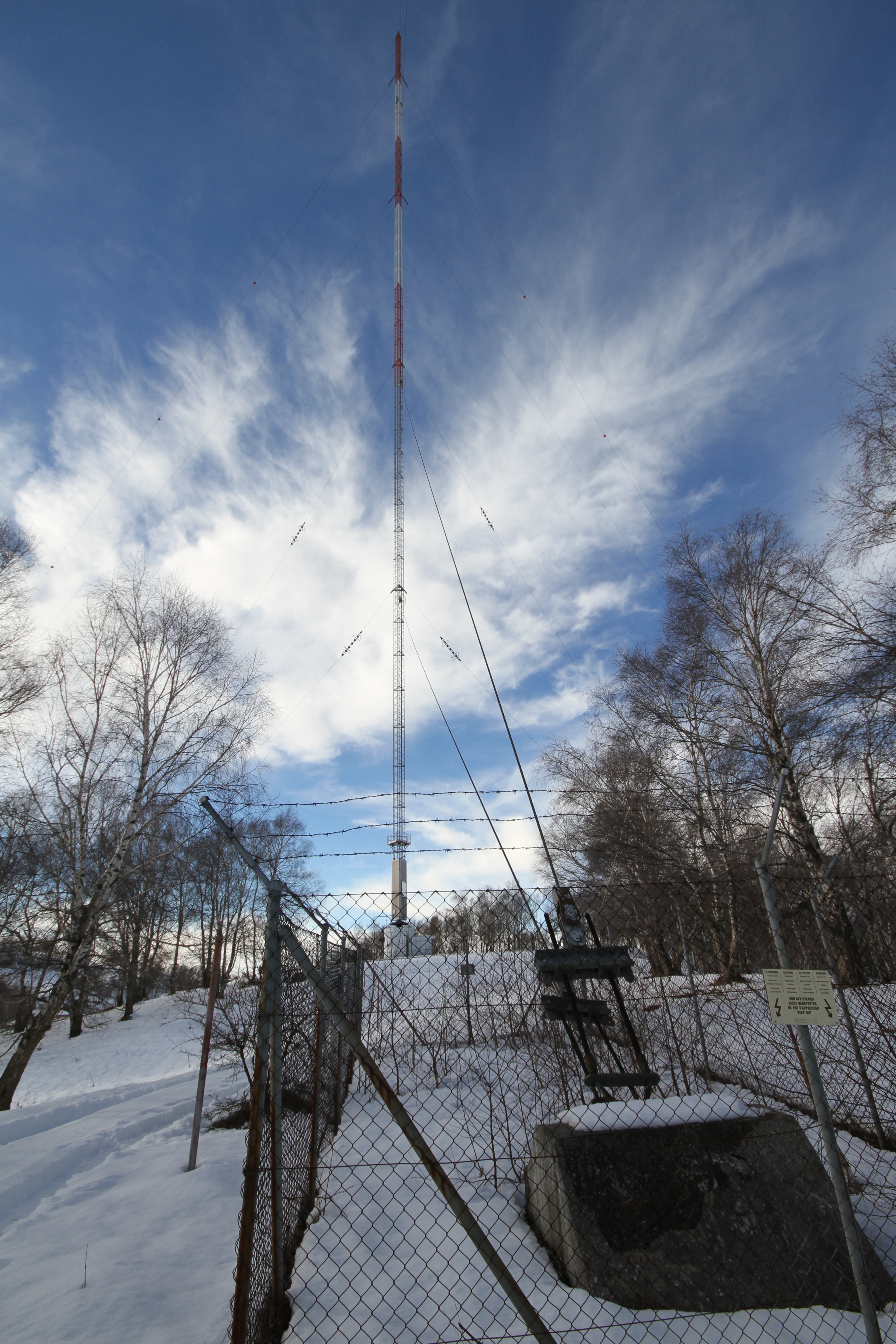
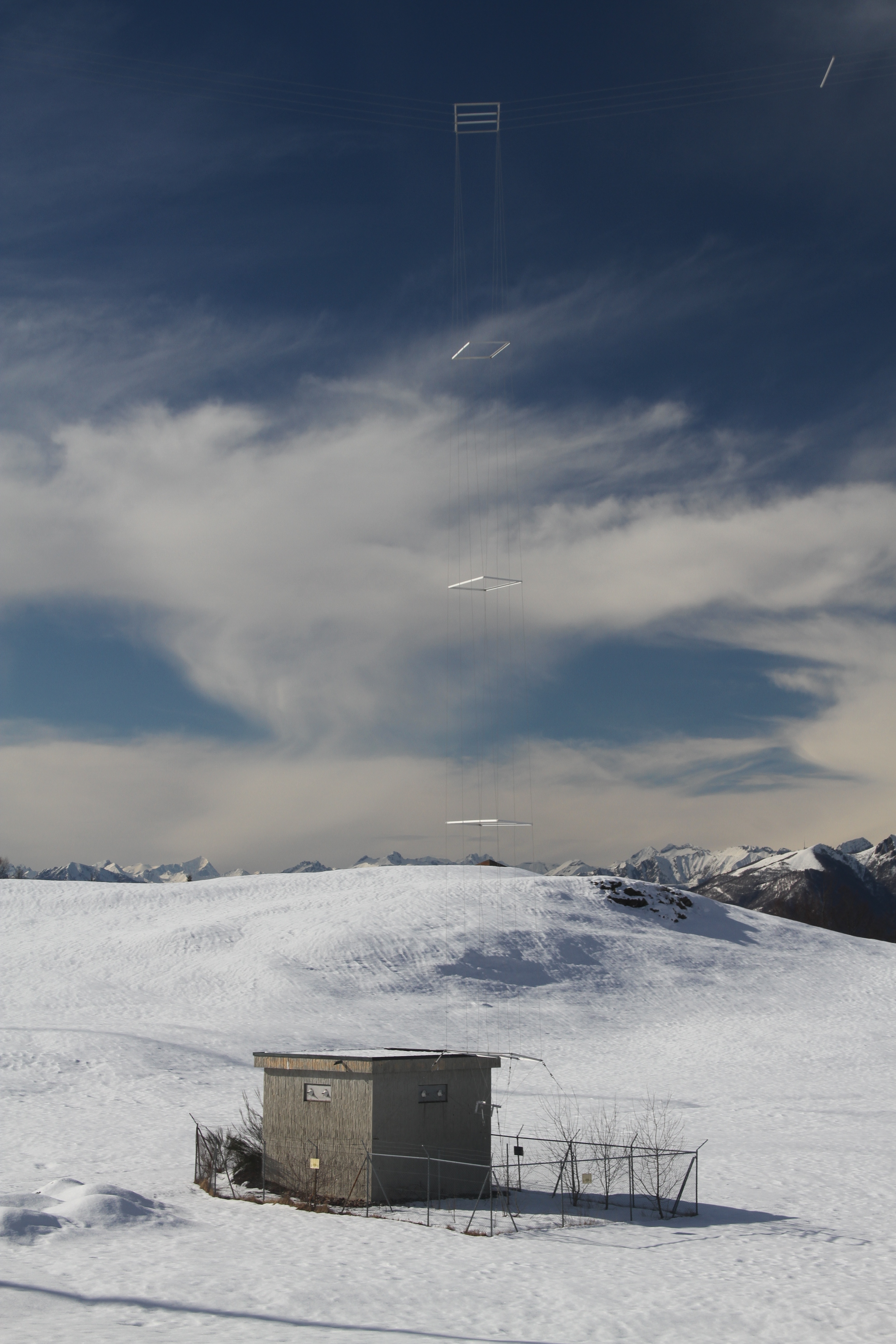
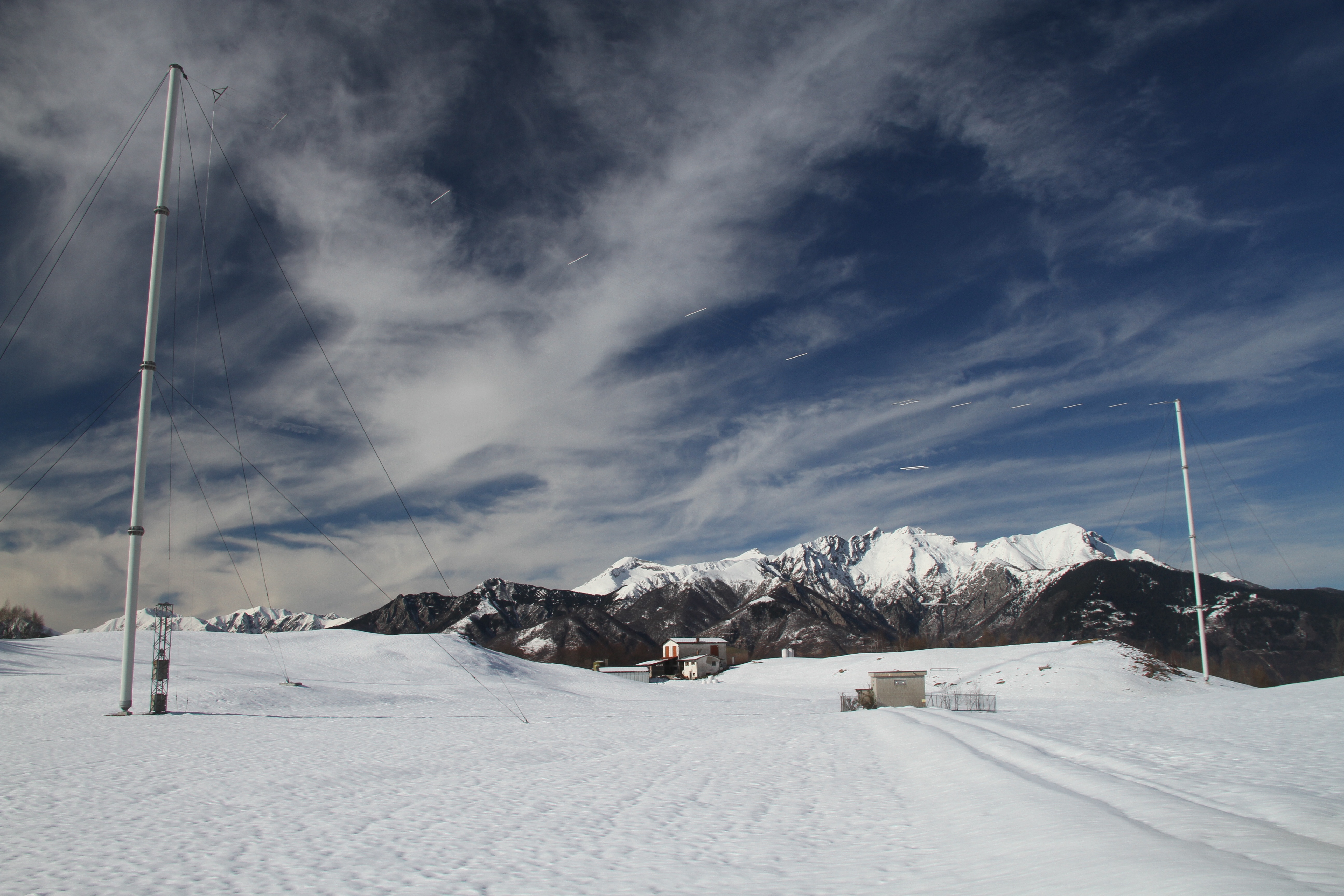 South view of the spare antenna. (Feb. 2011) |
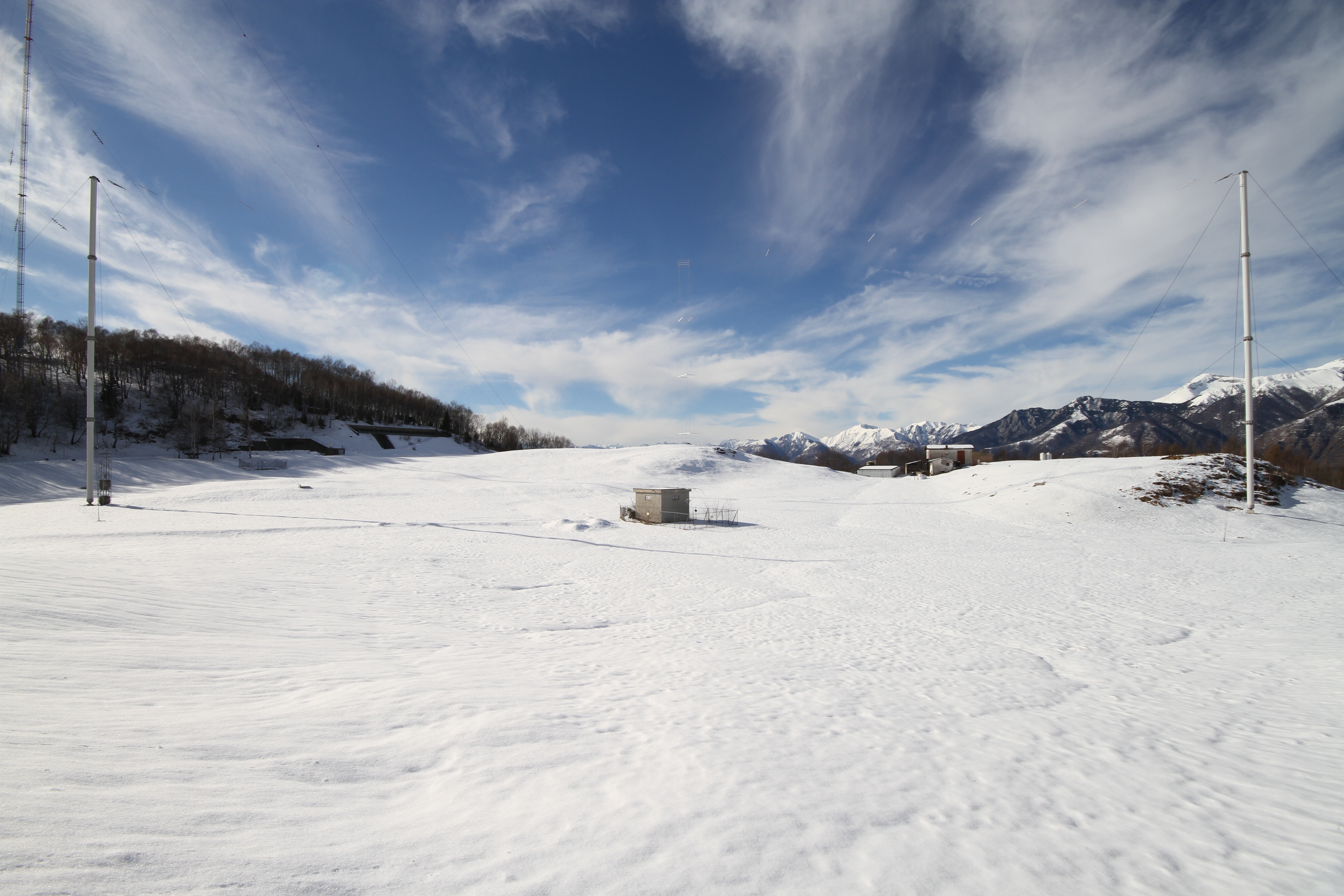 East view of the spare antenna. (Feb. 2011) |
 West view of the spare antenna. (Feb. 2011) |
 Mast and non-conductive guy wires. (Feb. 2011) |
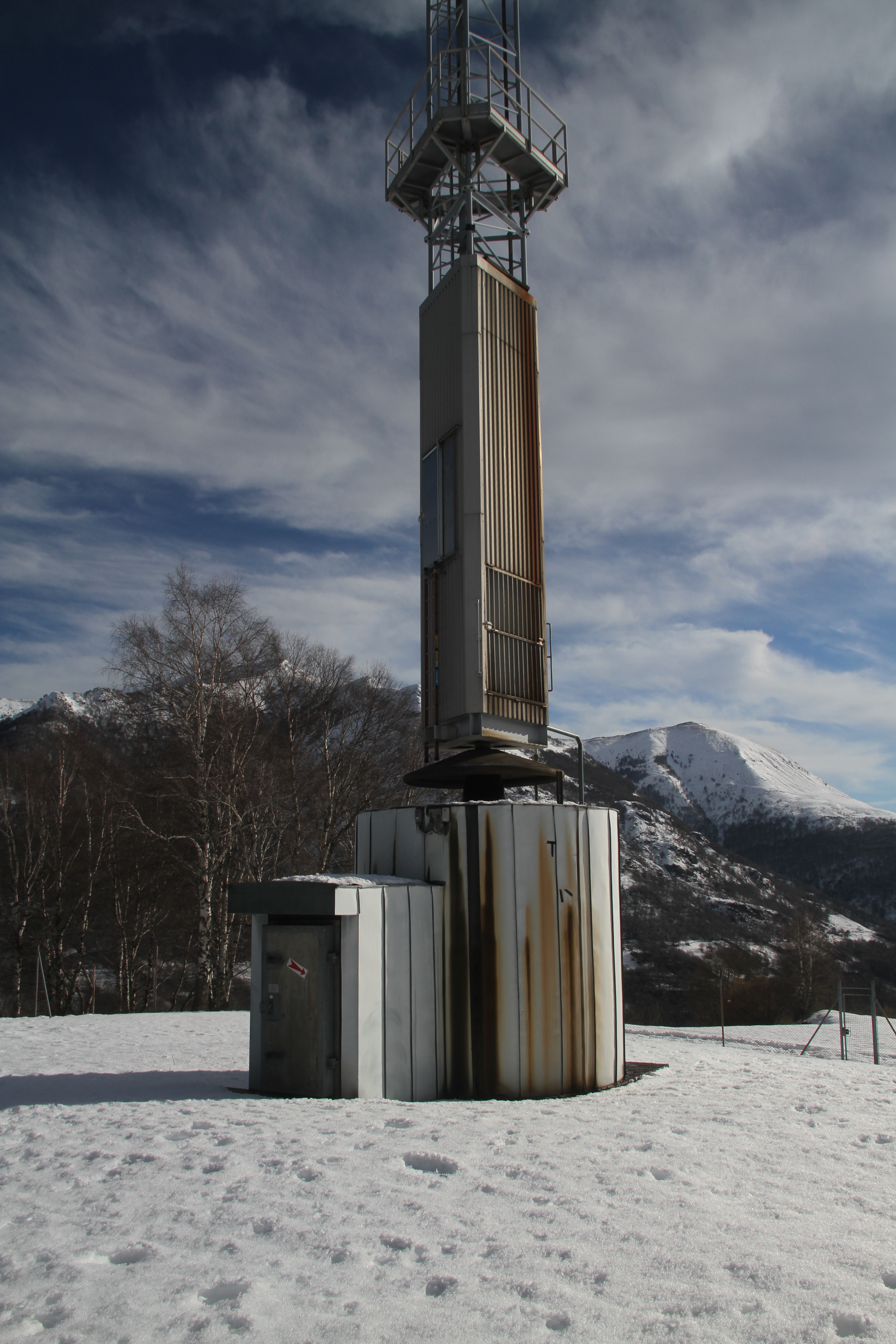
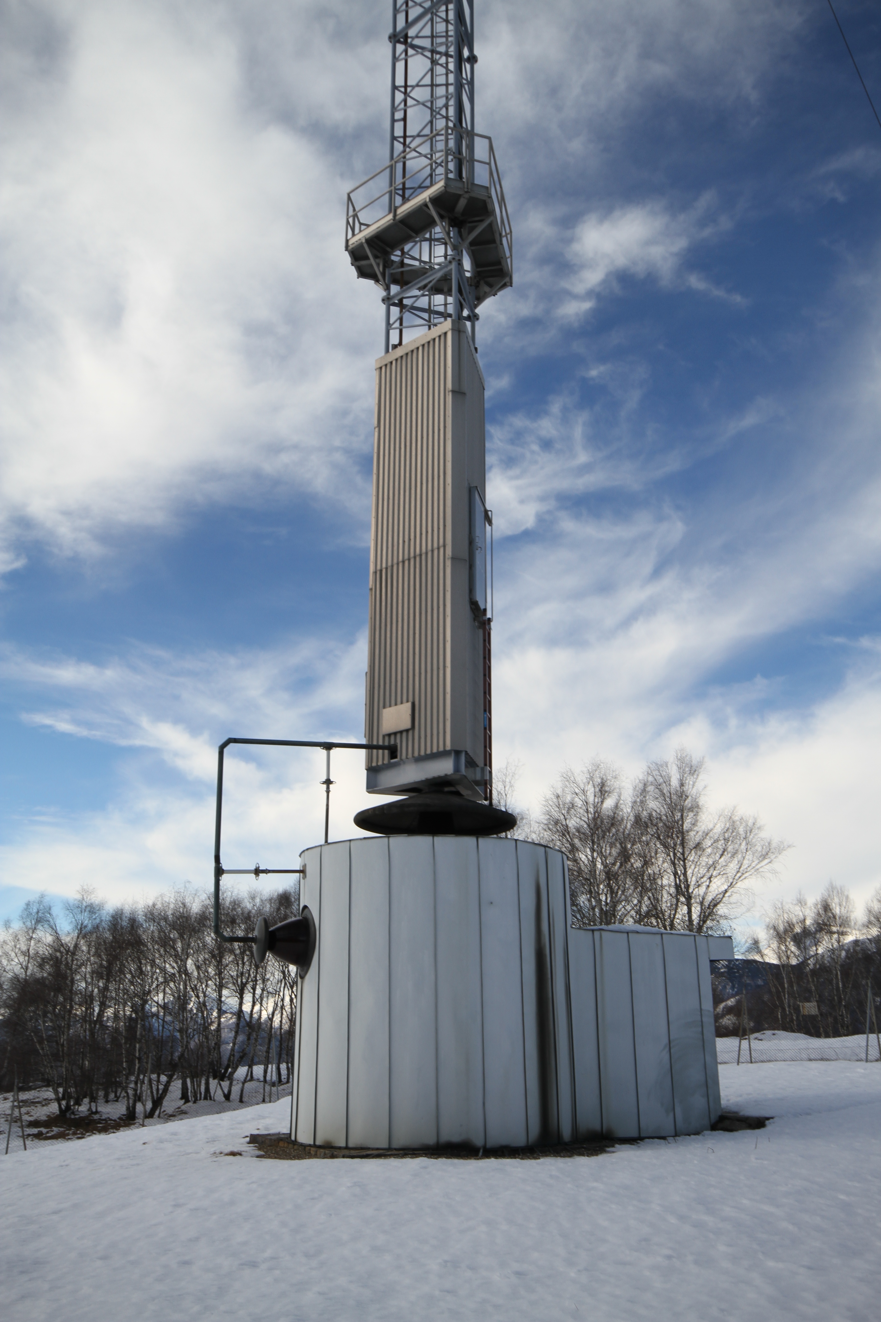
 Match box, feed point and vertical arm of the T. (Feb. 2011) |
 Feed point close up. (Feb. 2011) |