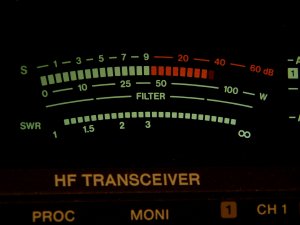
The S-meter is an instrument present on the majority of radio receivers that measures the strength of the signal that is being received, and uses a special unit: the S-point. S-points are often used for RST reports.
S-points go from S1 to S9 and each S-point is defined as a 6 dB change in signal strength. This means that each time the voltage is halved (–6 dB) the signal strength decreases by one point. S9 is already a very strong signal, but to describe larger signals, steps of 10 dB are used instead of 6 dB, noted "S9+20" meaning 20 dB above S9.
Today two reference values exist: for frequencies below 30 MHz, S9 is defined as a voltage of 50 μV over 50 Ω at the receiver antenna connector; for frequencies above 30 MHz, S9 is defined as a voltage of 5 μV over 50 Ω at the receiver antenna connector. This refers to an unmodulated carrier signal (N0N) that uses almost no bandwidth; in case of real signals using a given bandwidth, this definition may not be enough since a smaller receiver bandwidth allows a weaker minimum detectable signal, but S-points are still a good tool for comparing received signals.
| Signal strength |
Relative intensity |
Received voltage |
Received power (Zc = 50 Ω) |
||
| S1 | –48 dB | 0.20 μV | –14 dBμV | 790 aW | –121 dBm |
| S2 | –42 dB | 0.40 μV | –8 dBμV | 3.2 fW | –115 dBm |
| S3 | –36 dB | 0.79 μV | –2 dBμV | 13 fW | –109 dBm |
| S4 | –30 dB | 1.6 μV | 4 dBμV | 50 fW | –103 dBm |
| S5 | –24 dB | 3.2 μV | 10 dBμV | 200 fW | –97 dBm |
| S6 | –18 dB | 6.3 μV | 16 dBμV | 790 fW | –91 dBm |
| S7 | –12 dB | 13 μV | 22 dBμV | 3.2 pW | –85 dBm |
| S8 | –6 dB | 25 μV | 28 dBμV | 13 pW | –79 dBm |
| S9 | 0 dB | 50 μV | 34 dBμV | 50 pW | –73 dBm |
| S9+10 | 10 dB | 160 μV | 44 dBμV | 500 pW | –63 dBm |
| S9+20 | 20 dB | 500 μV | 54 dBμV | 5.0 nW | –53 dBm |
| S9+30 | 30 dB | 1.6 mV | 64 dBμV | 50 nW | –43 dBm |
| S9+40 | 40 dB | 5.0 mV | 74 dBμV | 500 nW | –33 dBm |
| S9+50 | 50 dB | 16 mV | 84 dBμV | 5.0 μW | –23 dBm |
| S9+60 | 60 dB | 50 mV | 94 dBμV | 50 μW | –13 dBm |
| Signal strength |
Relative intensity |
Received voltage |
Received power (Zc = 50 Ω) |
||
| S1 | –48 dB | 20 nV | –34 dBμV | 7.9 aW | –141 dBm |
| S2 | –42 dB | 40 nV | –28 dBμV | 32 aW | –135 dBm |
| S3 | –36 dB | 79 nV | –22 dBμV | 130 aW | –129 dBm |
| S4 | –30 dB | 160 nV | –16 dBμV | 500 aW | –123 dBm |
| S5 | –24 dB | 320 nV | –10 dBμV | 2.0 fW | –117 dBm |
| S6 | –18 dB | 630 nV | –4 dBμV | 7.9 fW | –111 dBm |
| S7 | –12 dB | 1.3 μV | 2 dBμV | 32 fW | –105 dBm |
| S8 | –6 dB | 2.5 μV | 8 dBμV | 130 fW | –99 dBm |
| S9 | 0 dB | 5.0 μV | 14 dBμV | 500 fW | –93 dBm |
| S9+10 | 10 dB | 16 μV | 24 dBμV | 5.0 pW | –83 dBm |
| S9+20 | 20 dB | 50 μV | 34 dBμV | 50 pW | –73 dBm |
| S9+30 | 30 dB | 160 μV | 44 dBμV | 500 pW | –63 dBm |
| S9+40 | 40 dB | 500 μV | 54 dBμV | 5.0 nW | –53 dBm |
| S9+50 | 50 dB | 1.6 mV | 64 dBμV | 50 nW | –43 dBm |
| S9+60 | 60 dB | 5.0 mV | 74 dBμV | 500 nW | –33 dBm |
Older receivers were calibrated using the old standard that defined S9 as a voltage of 100 μV instead of 50 μV over 50 Ω at the receiver antenna connector.
Usually S-meters in amateur radio equipment are not calibrated and are not very precise. S-meter readings may also vary from one band to another and it's always interesting to check an S-meter with a precise generator and a step by step attenuator.
| [1] | Wolfgang Link, DL8FI. Metodi di misura per radioamatori. Franco Muzzio & C. editore, 1978, sezione 3.9. |
| Home | Electronics | Index | Page hits: 137578 | Created: 10.1999 | Last update: 10.2013 |