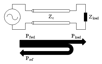
A generator is delivering power to a load though a transmission line. If the impedance of the line doesn't match the impedance of the load, a reflection takes place and some of the power is reflected back.
When a wave travels on a transmission line and finds an impedance mismatch, part (or all) of it is reflected back in the opposite direction. This is typically what happens when a cable is connected to an antenna: if the antenna impedance does not perfectly match the line impedance, a reflection takes place and some of the power that the transmitter is sending to the antenna is reflected back.
A generator is delivering power to a load though a transmission line.
If the impedance of the line doesn't match the impedance of the load, a
reflection takes place and some of the power is reflected back.
When both a forward and a reflected waves travel simultaneously with opposite directions on a transmission line, the resulting wave, being the superposition of the two, is called a standing wave.
Having standing waves on a transmission line is not necessary a bad thing, but transmitters usually do not like receiving back part of the power they deliver. So, to keep this phenomenon under control, many tools exist like impedance meters, impedance bridges, network analyzers, SWR-meters, reflectometers, and so on. But they don't always quantify it in the same way: the goal of this calculator is to easily convert from the different ways of quantifying reflected waves.
Please remark that for simplicity here we don't consider what happens to the reflected wave when it reaches the generator. It's most probably reflected back because generators usually do not absorb power, but this is another topic.
The root cause of wave reflection is an impedance mismatch. This usually happens where a connection is made between a cable and a load (antenna), but can also happen along the cable itself (if damaged or spliced). Matching networks (antenna tuners) are often used to match the impedances and reduce reflections. So, if we know the characteristic impedance of the line Zc and the load impedance Zl we can calculate the amount of power that is reflected back. Please remark that Zc is always a real number (note 1) while Zl can be complex. No reflection takes place when Zl is real and equals Zc. Any other value of Zl will reflect some power.
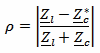
The reflection coefficient ρ describes the amplitude of the reflected wave in terms of voltage or current. It's always between 0 (no reflection) and 1 (total reflection), (note 2).
Now, ρ is a ratio of voltages (or currents). To find out the reflection in terms of power we have to square it:

Please remark that Pref is always less than Pfwd because a (passive) load cannot reflect more power than what it receives.
If forward and reflected powers are expressed in dBm instead of W, expressing the reflection coefficient in terms of return loss RL (in dB) is very handy:
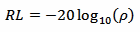
This is because the return loss (in dB) is just the forward power (in dBm) minus the reflected power (in dBm).
But the reflection can also be described in terms of the resulting standing wave. The voltage standing waves ratio (VSWR or often simply SWR) is the ratio between the maximum and the minimum amplitude (voltage or current) of the standing wave.

The VSWR goes from 1:1 (no reflection) to ∞:1 (total reflection).
The amount of VSWR that can be tolerated by a transmitter is long debate. Of course, applying the specifications of the transmitter manufacturer is always a good idea. Often, but not always, antenna manufacturers specify their bandwidth for a return loss better (higher) than 10 dB, roughly corresponding to a VSWR better (lower) than 2:1, implying that this should be good enough. So, when no better figure is available, aiming for 10 dB or 2:1 is a good starting point.
To use this calculator, enter one of the following data:
Then click the "Calculate" button next to the value you just typed to compute the others. Unfortunately, an infinite combination of impedances gives the same VSWR and is therefore not possible to calculate the impedance that originated the reflection starting from the other parameters. The same apply to the forward and reflected power. "Infinity" can be entered for VSWR or RL, but it's case sensitive and must be type as shown.
Let's look at an example: the following picture is taken from an SWR meter connected on the coaxial line between a transmitter and an antenna. On the scale on the left we can read a forward power Pfwd (travelling from the transmitter to the antenna) of 8.5 W. On the scale on the right we can read a reflected power Pref (travelling back to the transmitter) of 0.25 W.
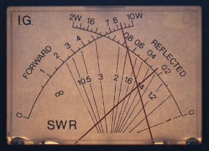
By entering Pfwd = 8.5 W and Pref = 0.25 W in this calculator, in one click we find the power ratio ρ2 = 0.29, the reflection coefficient ρ = 0.17, the voltage standing wave ratio VSWR = 1.4 and the return loss RL = 15 dB. By looking at the picture of the analog meters, we can see that the two needles cross very close to the 1.4 WSWR line, confirming our result (the VSWR grid of this meter is not very precise, this calculator is much better).
Actually, the characteristic line impedance Zc is a complex number. In theory, it's only real for lossless lines. In practice, however, for reasonably low-loss lines like the vast majority of common transmission lines, the imaginary part can be neglected. I have never seen a cable catalogue specifying a complex impedance for their products... And by the way, the whole VSWR idea, is only defined for lossless lines, but used in practice for low-loss lines.
Actually ρ is a complex number describing the amplitude and the phase of the reflection and is calculated as follows:

To keep things simple, here we consider only its absolute value (modulus).
| [1] | M. Walter Maxwell, W2DU. Reflections II, Transmission Lines and Antennas. Worldradio Books, 2001, Chapters 1, 5 and 6. |
| [2] | Fred Gardiol. Traité d'Électricité, Vol. III: Éelectromagnétisme. Presses Polytechniques et Universitaires Romandes, 1996, Section 3.6.3. |
| [3] | P.-G. Fontolliet. Traité d'Électricité, Vol. XVIII: Systèmes de télécommunications. Presses Polytechniques et Universitaires Romandes, 1996, Section 3.2. |
| [4] | The ARRL Antenna Book, 19th edition. American Radio Relay League, 2000, Pages 7-18, 9-1, 24-1..24-11. |
| Home | Electronics | Index | Page hits: 123908 | Created: 09.2000 | Last update: 11.2012 |