When designing an antenna, the desired gain and bandwidth are usually key parameters. Now, these parameters depend on the size of the antenna. Experience shows that high gain antennas are bigger than low gain ones. For example a Yagi-Uda antenna has much more gain than a dipole but it's also considerably larger. Experience also shows that high bandwidth antennas are much larger than narrowband ones. For example, a log-periodic antenna has more bandwidth and less gain than a Yagi-Uda of similar size.
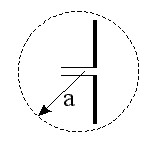
To simplify the design process, it's interesting to know beforehand, what is the maximum gain and bandwidth we can obtain for a given volume (and wavelength). Fortunately a very interesting article describes this relationship [1]. The volume is modeled with a sphere of radius a completely containing the antenna, as shown in the diagram below:
The author shows that the maximum gain of a lossless antenna completely filling this sphere is given by:

Where k is the wave-number and is given by:

Where λ is the wavelength, calculated with the usual equation:

And c0 is of course the speed of light, c0 = 299'792'458 m/s.
This gain considers a perfect lossless antenna completely filling the sphere; a real antennas will have losses and probably will not fill the whole volume. The result is that the gain will be lower than the one found here.
There is another interesting document [2] that establishes a relation between the volume occupied by an antenna and its quality factor Q, where the following equation can be found:
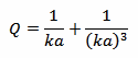
Where a and k are the same as above. To implement this equation in the calculator below, a numerical algorithm (Newton's method [3]) is used to solve it for ka.
Then, if Q>>1, we can calculate the maximum bandwidth BW with the following formula:

But there are some limitation on the use of this formula: first, it only applies to linearly polarized antennas, then, it assumes that the antenna is lossless. Real antennas have losses, and the effect is to widen the bandwidth (and reduce the gain).
Unfortunately, the condition Q>>1 only applies to very small antennas, so the usefulness of this formula is somehow limited.
Enter the frequency f and one other value (either a, G, Q or BW) and click the "Calculate" button next to it to compute the three other values.
Let's have a look at a few examples: in the following picture we have a simple dipole designed to operate at 2.45 GHz. It's 64 mm long and has a gain of 2 dBi. With the calculator, we set a to 32 mm and we get a theoretical maximum gain of 7.8 dBi. The real antenna is far from reaching the theoretical limits but, on the other hand, it does not completely fill the sphere and uses only a small fraction of the volume. We also find a Q of 0.834, which is too small to deduce any bandwidth.
Another antenna is shown in the picture below: it's a small GSM dual band 900 and 1800 MHz printed antenna. It's 43×6 mm2 big and is specified by its manufacturer for 0 dBi gain. Bandwidth is not specified, but the GSM standard requires 70 MHz for the 900 MHz band and 170 MHz for the 1800 MHz one.
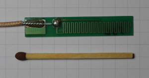
Setting a to 22 mm, for the 1800 MHz band, we find a theoretical maximum gain of 3.7 dBi and a maximum Q of 3, which is still too low for deducing any bandwidth. Repeating the same calculation for the 900 MHz band, we find a theoretical maximum gain of 0 dBi and a maximum Q of 16.4 providing a maximum bandwidth of 55 MHz. This may look in agreement with the data specified by the manufacturer, but I suspect the announced gain of 0 dBi is too good to be true. Compared to other antennas of similar size, a real gain of –4 dBi would be more realistic, but I'm not equipped for measuring the gain. Concerning the bandwidth, some losses are certainly present and there is no doubt this antenna covers the required 70 MHz, at the expense of some gain.
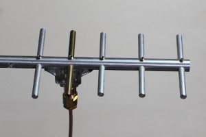
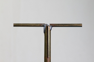
Finally, in the picture below, we have a Yagi-Uda antenna designed for 2.45 GHz. It has a gain of 6 dBi and is 95×60 mm2 big. With the calculator we find a theoretical maximum gain of 11 dBi and maximum Q of 0.45.
| [1] | L. J. Chu. Physical limitations of omni-directional antennas. Journal of Applied Physics, vol. 19, December 1948. Pages 1163-1175. |
| [2] | R. F. Harrington. Time-Harmonic Electromagnetic Fields. Electrical and Electronical Engineering, McGrow-Hill, New York, 1961. |
| [3] | J. Rappaz. Analyse numérique. Notes de cours: Leçons 1 à 10, École Polytechnique Fédérale de Lausanne, 1994. Pages 64-66. |
| Home | Electronics | Index | Page hits: 109291 | Created: 09.2000 | Last update: 11.2012 |