A CW straight key is always a nice mechanical piece. Some people collect them, some other just have one magnificent piece in their shack connected to their favorite radio. Homebrewing a CW key is quite a long job, but going on air with our own key or showing it to our friends is really a good source of satisfaction.
I wanted to build a small, light and portable key, but I wanted it also to look good and feel good when operated. No compromises, a good quality design and a simple construction.
In order to achieve a good looking key, some mechanical workshop machines are required: at least a press drill with an X-Y vice, but a simple milling machine (and a lathe, maybe) are much better. But no need for digital machines, an old manual milling machine is more than enough.
To make a portable key, it's important to reduce the size and the weight, but a light key may be unstable. To prevent any stability problem, the key was designed in such way that the force applied on the knob falls within the surface of the base preventing any torque and removing any constraint on the minimum weight. In other words, the knob is located within the surface of the base. The overall dimensions are 60 x 35 x 65 mm3 and weights 100 g.
The initial idea was to use brass for all the pieces except the knob, but to reduce weight I considered aluminum and finally choose POM plastic (also known as polyoxymethylene or polyacetal) because its lighter, easy to machine and robust enough. But the same design could be used with metal as well with no modification.
The pivot is made with two ball bearings and a steel shaft to ensure a smooth movement of the main arm. The bearings were ordered by Conrad (part number 295604) and are normally intended for model building. They have an external diameter of 8 mm, an internal diameter of 4 mm and a height of 3 mm. The steel shaft was also ordered by Conrad (part number 237060), has a diameter of 4 mm h6 and was cut to a length of 22 mm. A small cone point screw (DIN 914) M3 x 4 mm in the main arm holds the shaft in place during assembly. Once the key is fully assembled the shaft is prisoner between the side brackets, but still it's a good idea to keep this screw in place. Two o-rings with an internal diameter of 4 mm and a thickness of 1 mm hold the bearings in place and prevent them from touching the central arm.
The two side holders are fixed on the base with four socket head cap screws (DIN 912) M3 x 25 mm.
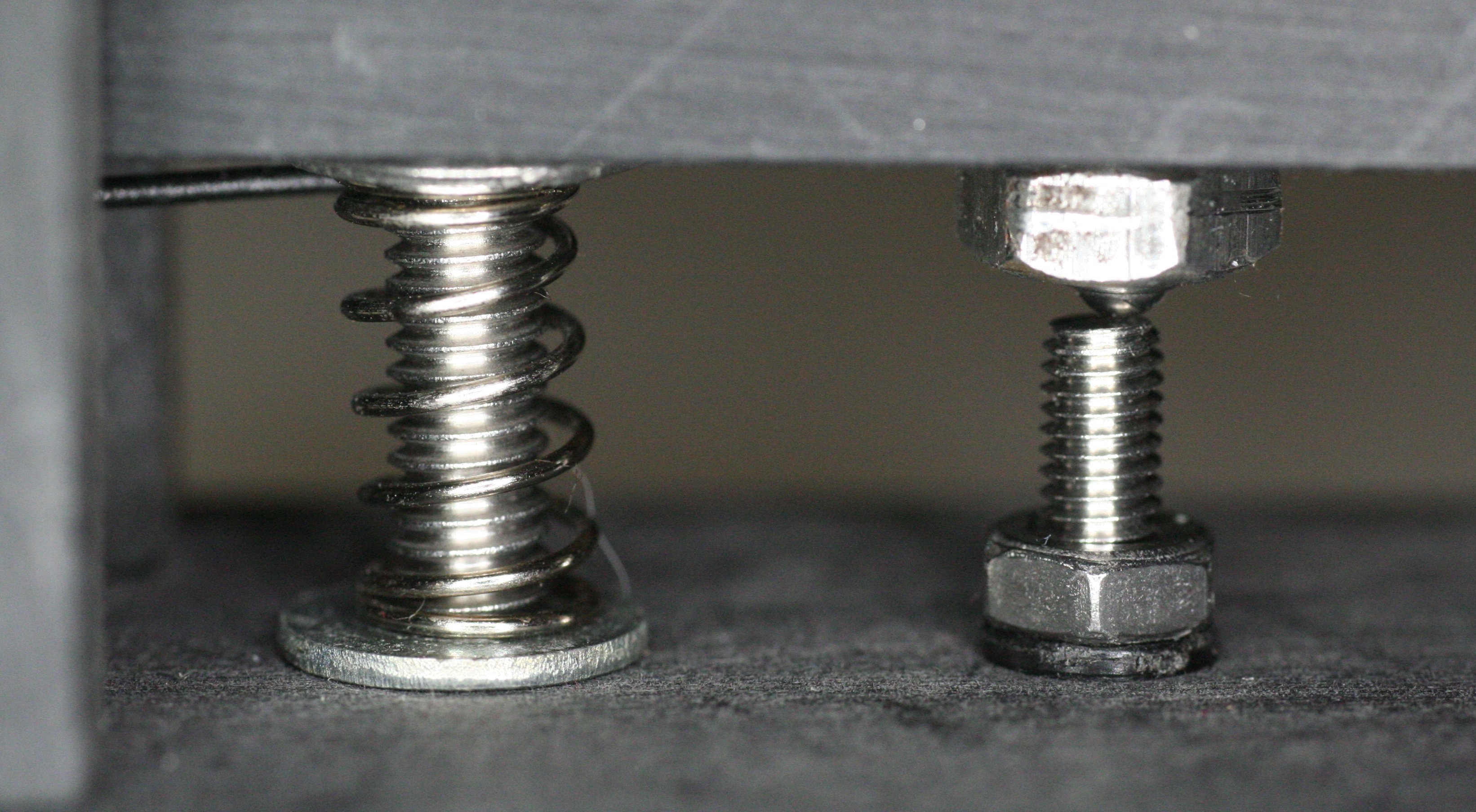
A small spring loads the main lever. I choose a small compression spring made by 5.5 turns of 0.5 mm steel wire with an internal diameter of 5 mm, a rest length of 14 mm and a rate of 0.93 N/mm. To reduce se size and keep the design simple, there is no explicit spring tension adjustment, but the tension can still be adjusted by manually adding some washers to compress the spring. The spring is held in place by a long socket head cap screws (DIN 912) M4 x 50 mm that is threaded in the base and controls the amplitude of the movement with a large knurled nut and a lock nut.
The contact is done between a cone point screw (DIN 914) M4 x 10 mm threaded in the main arm and a flat socket head cap screws (DIN 912) M3 x 16 mm fixed in the base. Unfortunately, I couldn't find any gold plated screw and I had to use stainless steel to prevent oxidation problems. The top cone point screw is simply threaded in the arm locked in place by a nut: since all the pieces of the key touch each other, this side of the contact must be connected to the ground if metallic parts are used. But even with metallic parts, the contact through the ball bearing and the shaft is not very good and a thin flexible wire should be used anyway. The lower screw is mounted with insulation washers and is connected to the hot side of the contact. On the rear side of the base, there is just the place for a small 3.5 mm "phone" connector.
Finally the knob was machined on a small lathe starting from a Ø20 mm POM bar and fixed to the main arm with a socket head cap screw (DIN 912) M3 x 16 mm. I think that even if the main body of the key is metallic and grounded, the knob should be in an insulating material such as plastic or wood. Another solution is to use a standard drawer knob available in any hardware store, but I choose to machine mine because I didn't want a "cheap" look.
Machining all the pieces is definitely the longest task, but the plans above should include enough details. Than it's just a matter of assembling all the pieces together. Everything can easely be disassembled if needed: no glue is used, and no part requires lubrication (not even the ball bearings).
The following exploded view could be handy:
Adjusting the tension of the spring requires some patience since one has to almost disassemble the whole key to add a washer to compress the spring, but this is just done once. I personally think the best compromise is to compress the spring to a length of about 8 mm (it's 14 mm at rest); the gap between the base and the arm is nominally 10 mm, so just add enough washers for a total thickness of 2 mm. Anyway, this adjustment is very personal and you may like a softer or harder key.
On the other hand, adjusting the gap between the contacts is very easy: just turn the top cone point screw and lock it in place with its lock nut when finished. Personally I like a gap of about 0.2 mm, but again this adjustment depends on the feeling you're trying to achieve and you may prefer a different gap.
The pictures below show the finished key and are probably more clear than the plans. If desired, POM can accept a high polish; brass or aluminum can be polished as well. Personally, I don't like a polished key, because it always get "dirty" with fingerprints: I choose a matt finish by rubbing all the parts with sandpaper, but again, this choice is very personal.
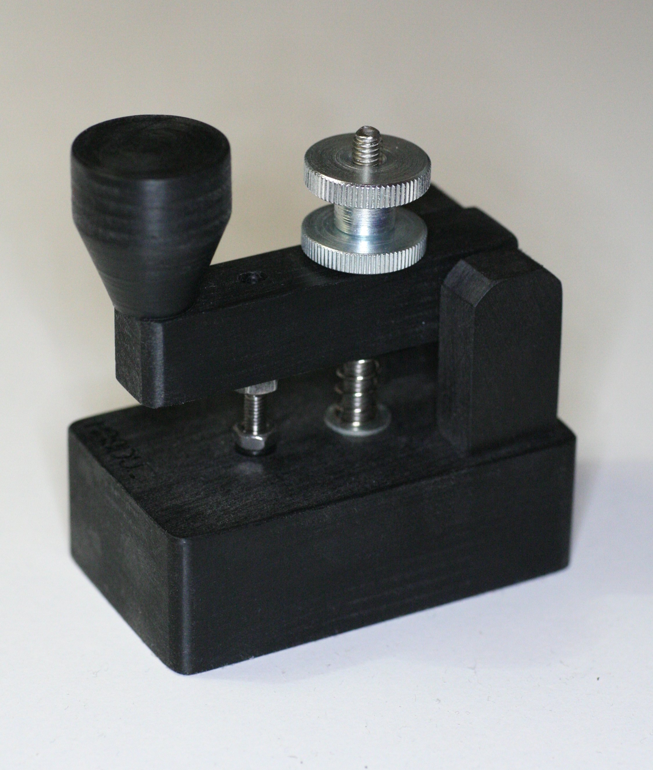
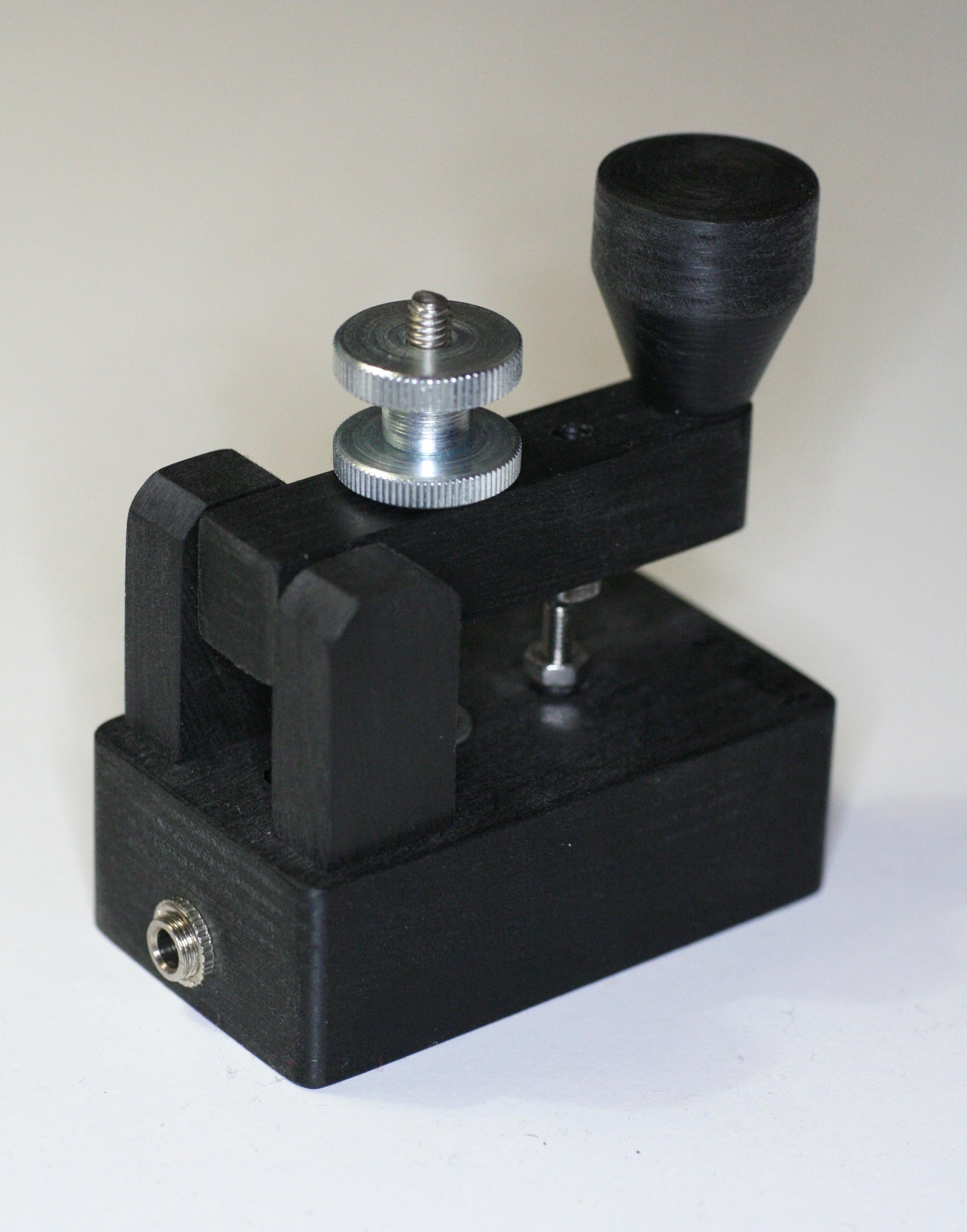
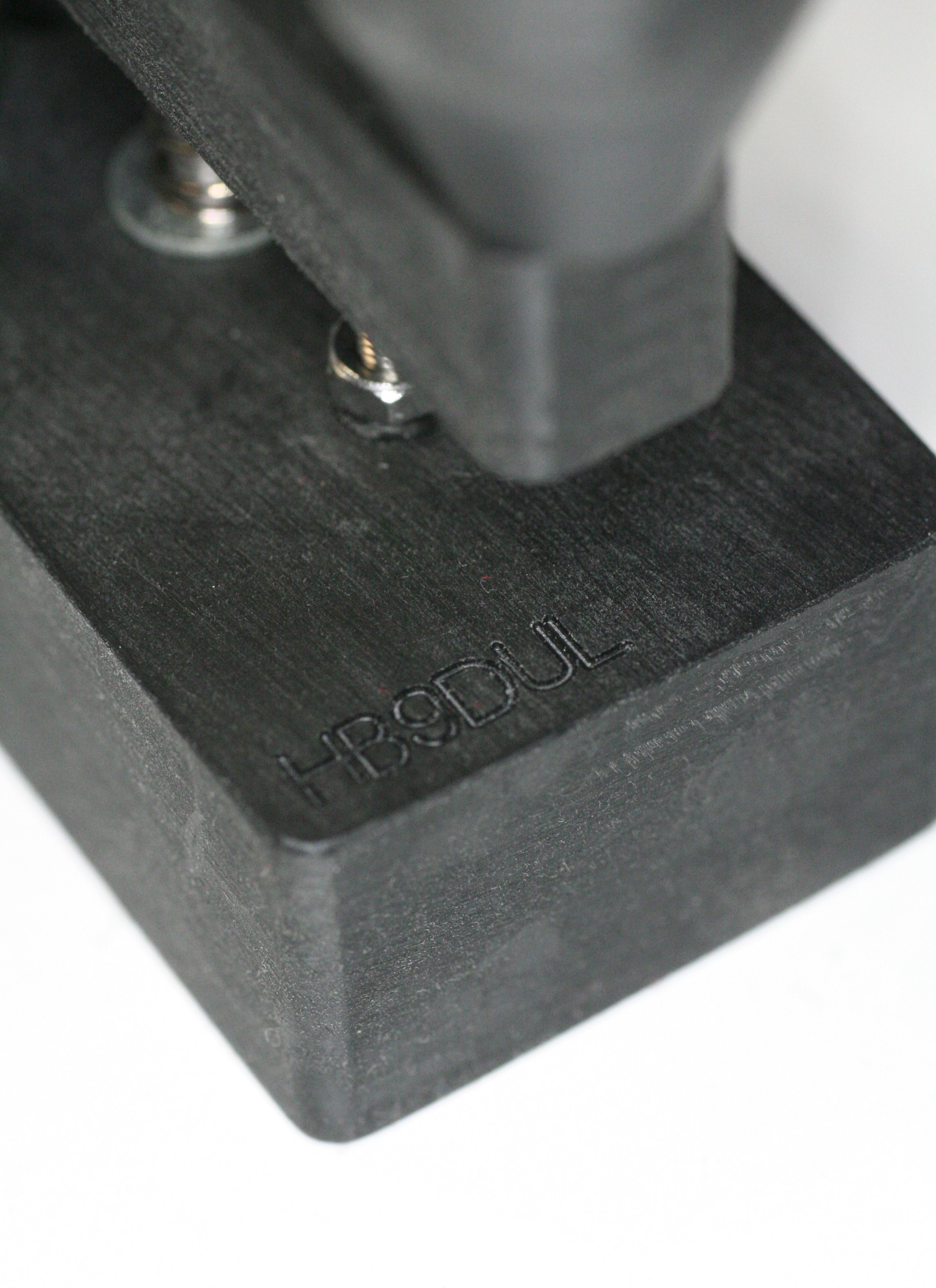
Since the base has a flat surface, it's easy to engrave your call sign. Also remark the little black wire that connects the upper cone point screw to ground.
A CW straight key is not just a switch, it's a complex mechanical device that results from a balance between many factors like the force required to operate it, the way the lever hits the contact, the reliability of the contacts, the ergonomy, the weight, the physical aspect, the mechanical complexity, the cost or the time required to build it, just to list a few of them. This key responds to the best compromise I could find for portable use.
| Home | Mechanics | Page hits: 025992 | Created: 12.2012 | Last update: 12.2012 |