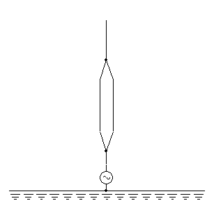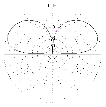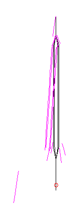
In order to get a rough idea of the performance of such antenna, it has been simulated and the gain, the radiation pattern, the antenna impedance and the current distribution has been calculated. Precise data about the structure are not available and the dimensions have been estimated via observations on site. No antenna performance data is available and therefore the result of the simulation cannot be checked against the reality and may be considerably wrong, but the figures look plausible and are reported and commented below.
The spare antenna of the Savièse transmitter is an aluminum tower, whose height has been estimated in 16 m. Its base is insulated from ground and connected to the feeder via a matching network in a waterproof box. In its central portion, the mast is surrounded by a wire cage making it appear thicker. The mast is hold in place by four groups of 3 guy cables. All guys are interrupted several times by insulators and their length is very short compared to the wavelength. For this reason the current in the guys will be very small meaning that they will have very little influence on the antenna radiation and have been ignored for this simulation. Transmission frequency is 1485 kHz, one wavelength is 202 m and a quarter wavelength is 50.5 m.

Ground conductivity has a very big influence on the gain (the higher the conductivity the higher the gain), the elevation angle (the higher the conductivity the lower the angle) and the impedance. Unfortunately no information about ground conductivity is available. It's not known if this antenna buried radials or not, but in any case the presence of buildings in close proximity and the terrain configuration suggest that a very good ground system is not present, so a value of 2 mS/m has been arbitrary chosen.
The simulator doesn't like the cage structure and has problems in getting a reasonable current distribution. In order to simplify the problem the central conductor in the cage has been removed forcing the current to flow in the external cage wires. The simulation shows that this modification has no influence on the gain or the radiation pattern and that the changes in the feed impedance are minor (less than 5 %). With the modified cage, the simulation shows a gain of –1.3 dBd (including losses), an elevation angle of 27° and a half power beam-width of 47°. The very low gain and high radiation angle are plausible considered the small size of the antenna compared to a λ/4 monopole, which would be 50 m high.

The current distribution on the mast is typical for a short antenna. The maximum current is 22 A at the base. The feed impedance is (2 – j90) Ω, meaning that for a power of 1 kW, the feed current is about 22 A and the feed voltage is 7.2 kV. To have a comparison, 1 kW on a 50Ω resistive load requires a voltage of 223 V and a current of 4.47 A.

The simulation doesn't show a significant difference if the center conductor is removed inside the cage, so one may wonder what is the influence of the cage compared to a straight vertical antenna. If the cage is removed, the gain is almost the same (–1.3 dBd), the elevation angle drops to 23° and the half power beam-width is still 47°. The feed impedance is a bit higher (2.6 – j540) Ω changing feed voltage and current to 10.5 kV and 19.5 A for the same power. The current distribution on the mast is similar.
According to the above results, the cage doesn't look very useful, but the it could make that bandwidth of the antenna larger (thus, this has not been simulated) and helps in making the mast more rigid requiring less guy wires. It's also possible that the simulator gives incorrect results when simulating the cage, and because of the lack of real measured data concerning this antenna, this possibility cannot be verified.