In order to get a rough idea of the performance of such antenna, it has been simulated and the gain, the radiation pattern, the antenna impedance and the current distribution has been calculated. Precise data about the structure are not available and the dimensions have been estimated via observation on site. No antenna performance data is available and therefore the result of the simulation cannot be checked against the reality and may be considerably wrong, but the figures look plausible and are reported and commented below.
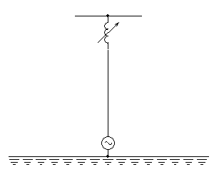
The antenna of the Prangins GLA transmitter is a short (very short) supported by non-conductive guy wires. It's height has been estimated at 13.5 m. The matching network is situated at the base and connects to the base of the mast, which is insulated from ground. On top of the mast there is a loading coil that allows adjusting the phase to make the antenna look longer and on top of the coil there is a capacitive hat that has the function. Transmission frequency is 375 kHz, one wavelength is 800 m and a quarter wavelength is 200 m.

Ground conductivity has a very big influence on the gain (the higher the conductivity the higher the gain), the elevation angle (the higher the conductivity the lower the angle) and the impedance. Unfortunately no information about ground conductivity is available. A value of 2 mS/m has been arbitrary chosen.
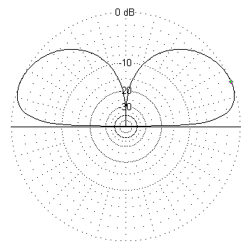
Before simulating the real antenna, a single mast with no loading coil and no capacitive hat has been considered. Its impedance is (0.12 – j2700) Ω almost only a 160 pF capacitor, a real nightmare to match to a transmitter. The gain would be 0.1 dBd (including losses), an elevation angle of 23° and a half power beam-width of 48°.
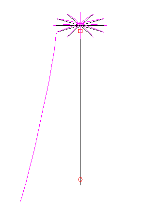
Than the capacitive hat has been added on top of the mast. The hat doesn't radiate because currents in its wire cancel each other, but contribute in increasing the current in the mast that is responsible for radiation. The size of the hat has been estimated in 4 m in diameter. The hat almost doubles the real part of the impedance which is now (0.21 – j1900) Ω, but still the antenna looks like a 220 pF capacitor. The gain would be 0.2 dBd (including losses), with the same elevation angle and half power beam-width. The current distribution is shown in the figure below:

Than a loading coil has been inserted right below the capacitive hat. By adjusting the coil it's possible to introduce a phase shift than makes the antenna look longer. Starting with 0 μH (short circuit) the inductance has been experimentally increased and the impedance recalculated. As the inductor increases, the real part of the impedance also increases and the imaginary part becomes less and less capacitive and reaches 0 around 1552 μH. At this point, the coil adds enough phase shift to make the antenna look like λ/4. The impedance is now (0.52 – j0.122) Ω, still very low but better to match. Concerning the radiation pattern, nothing has changed, the gain is still 0.1 dBd, the elevation angle 23° and the half power beam-width 48°.

Now a 1500 μH coil is quite big and we have to take into account its losses. Let's suppose a very good coil with a Q factor of 200. That means a series resistance of 18 Ω. Re-simulating the antenna with inductor losses gives a gain of –17 dBd, an elevation angle of 23° and a half power beam-width of 48°. It has to be remarked, that in all simulations of this antenna, the radiation pattern was the same; only the gain and the impedance changed, not the shape of the pattern. The impedance is now a much nicer (25 – j180) Ω but of all the power sent to the antenna, only 1.9 % is radiated and 98.1 % is wasted in the loading coil!
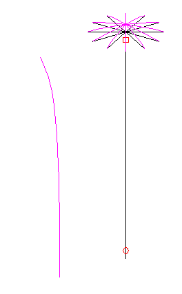
The current distribution of the complete antenna is shown in the figure below:
