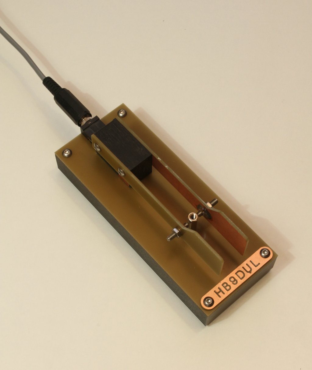
The PCB paddle fully assembled and operational (click to enlarge).
I've seen several implementations on the web and on radio magazines of iambic paddles made with PCB (Printed Circuit Boards) boards. The construction is very simple since there are almost no moving parts: no bearings, no springs, no axles; nothing. The elasticity of the material does the whole job. And there are plenty of scrap PCB material in almost any junk-box. So, I couldn't resist the temptation of building my own. Since I'm quite happy with the result, I decided to publish this page.
Everything is based on FR-4 material which it the most common material of PCBs. It's basically a glass-reinforced epoxy laminate sheet: it's hard but flexible, an excellent electrical insulator and can be sourced for a "low" price. Of course, this design will also work with different PCB materials, but you may have to adjust the dimensions to have the good force on the paddles. In this project, standard 1.6 mm (1/16") thick single layer FR-4 board is used. The copper on one side is used as conductive layer and for soldering brass nuts, but (almost) no etching is necessary.
The PCB paddle fully assembled and operational (click to enlarge).
No calculation on elasticity has been done: I just tried with different lengths and heights of PCB boards until I found the stiffness I liked most for my iambic paddle.
The overall dimensions are 50 × 125 × 40 mm3 and weights 188 g.
The paddles are two symmetrical pieces. The copper goes on the inside so that your fingers only touch the insulated epoxy side. The length and height that give the best feeling is too small for my fingers, so I enlarged the paddle on one end to improve ergonomy. A detail drawing of the pads is shown below:
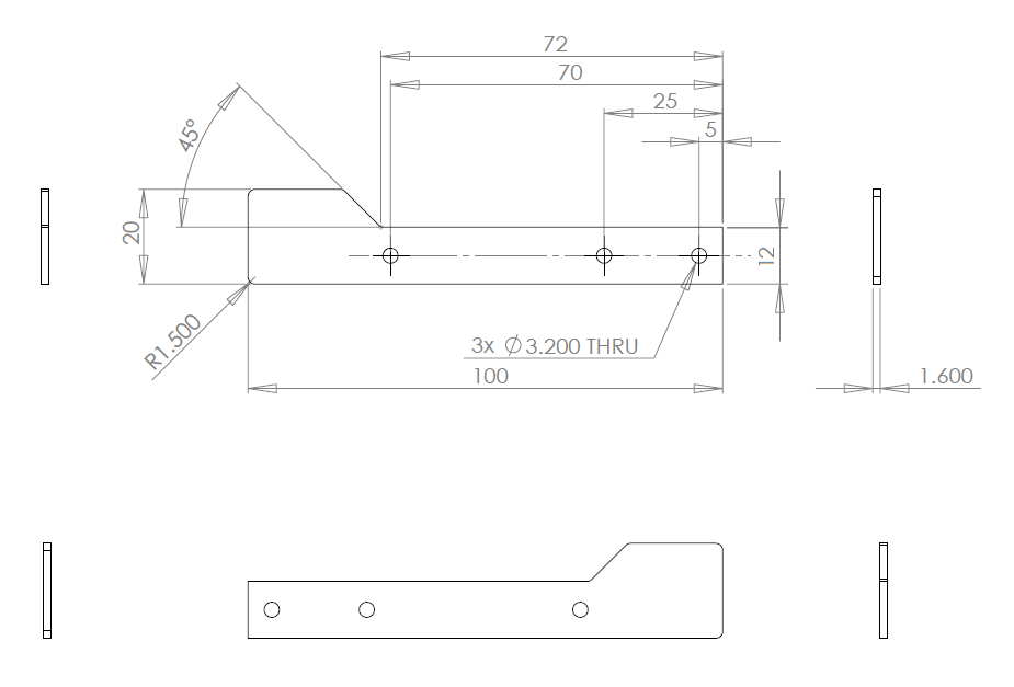
Detail drawing of the pad boards, all dimensions are in mm (click to
enlarge).
Cutting PCBs can be done with a hacksaw and a blade intended for metal. For drilling it, regular HSS drill bits do the job but won't last very long because the glass fibres in the board are very hard. Hard-metal drill bits work fine but are expensive, fragile and hard to source. On the other hand, simple HSS drill bits are cheap and can be re-sharpened afterwards: they are probably the best option. Cuts are than smoothed out with a flat file to achieve good looking pieces.
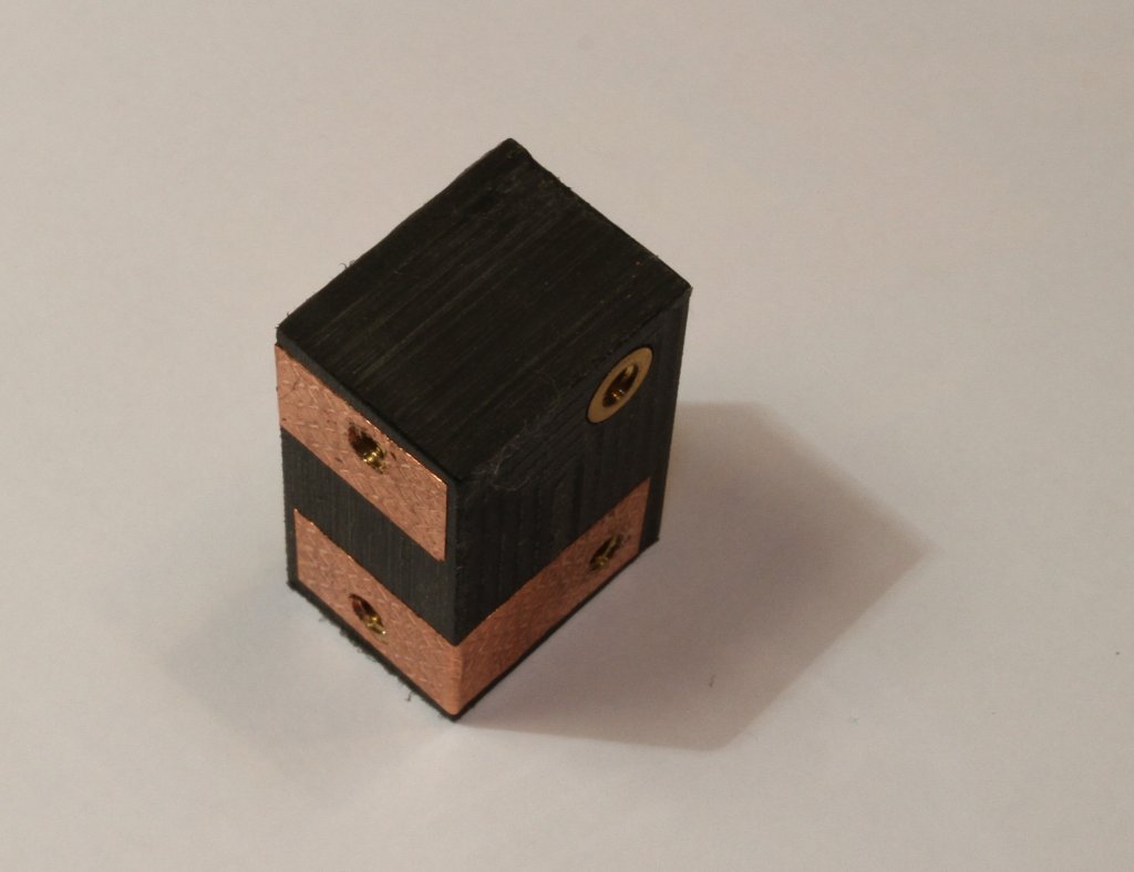
A brass M3 nut or threaded insert is soldered on the copper side of each paddle to hold the corresponding contact screws. I used cone point screws (DIN 914) M3 × 14 mm tightened in place with M3 nuts located on the other side of the PCBs. I used stainless steel screws to avoid oxidation and ensure a good electrical contact. Gold plated contacts would be better, but on one hand I didn't have any and on the other it would be too much for this cheap device. When the paddles are pushed sideways, the two cone point head screws make contact with a single nickel plated brass hexagonal standoff M3 × 20 mm mounted on the base PCB plate. The PCB paddles are not as precise as a true mechanical key and I prefer a larger gap than usual in the contacts, something between 0.5 and 0.7 mm, but this is very personal and can easily be adjusted.
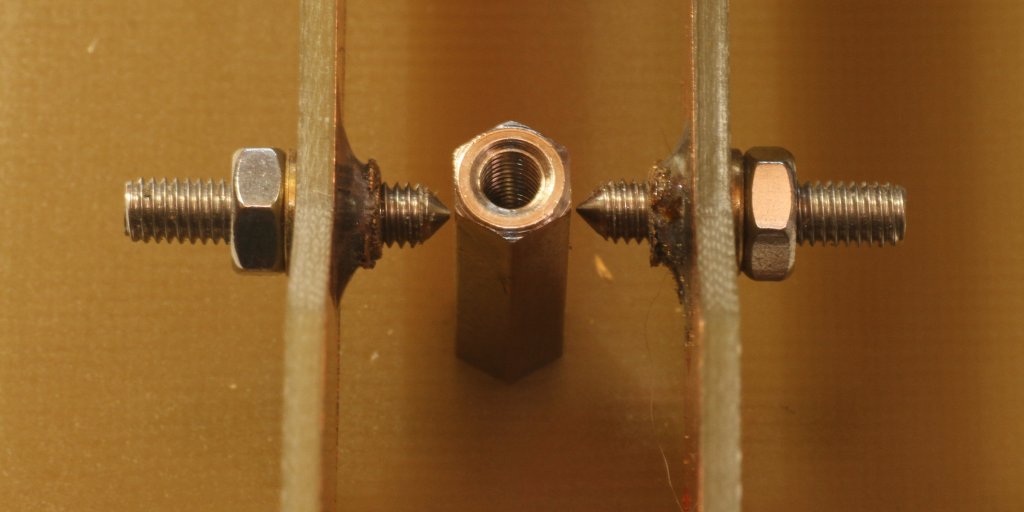
Closeup of the contacts (click to enlarge).
The two paddles are held in place by a plastic block mounted on the rear side of the assembly. It's made of POM (also known as polyoxymethylene or polyacetal) because it's robust and easy to machine. Any other plastic will do the job. Since it's a rectangular block, you don't need special tool to cut it: a meter saw and a press drill are enough (plastics are soft and can be cut with the same saw blades used for wood).
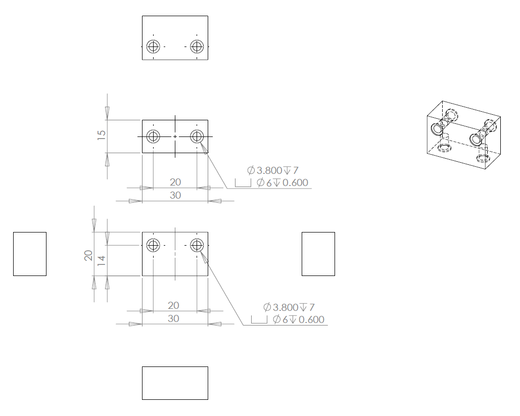
Detail drawing of the plastic stand block, all dimensions are in mm
(click to enlarge).
Of course, one could solder two wires directly to the paddles, but since we're building everything with PCBs, it would be nice to avoid wires at all, so I put a piece of self adhesive copper tape over the insulating block, bended in an L-shape, to make contacts between each paddle and the base board. Aluminium foil will work as well. The following picture is certainly more clear than this explanation...
The plastic spacer block with the two copper stripes used to connect
the paddles to the base (click to enlarge).
Instead of threading directly into the plastic, I drilled larger holes and press fitted M3 brass inserts. If you don't have a press, you can use a vice to push the inserts in place. Not only the screws holds better and the threads are not damaged by disassembling and reassembling frequently, but a good electrical contact is ensured between the copper stripes and the screws. Six M3 × 6 mm stainless steel ISO 7380-1 button head cap screws are used to mount this block, but similar types of screws can be used as well.
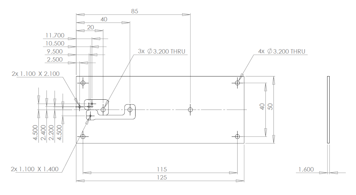
Detail drawing of the base board, all dimensions are in mm (click to
enlarge).
The base is also a rectangular piece of PCB on which the spacer block is fixed. This board can be etched to allow an electrical connection with a small 3.5 mm "stereo phone" connector; this will avoid any wire. The detail of the etching is only visible in the enlarged version of the base plate drawing. Usually the left paddles goes on the tip of the connector while the right goes on the ring. Left-handed people usually connect it the other way around. It's very easy to invert the paddles: just flip the two copper stripes on the spacer block.
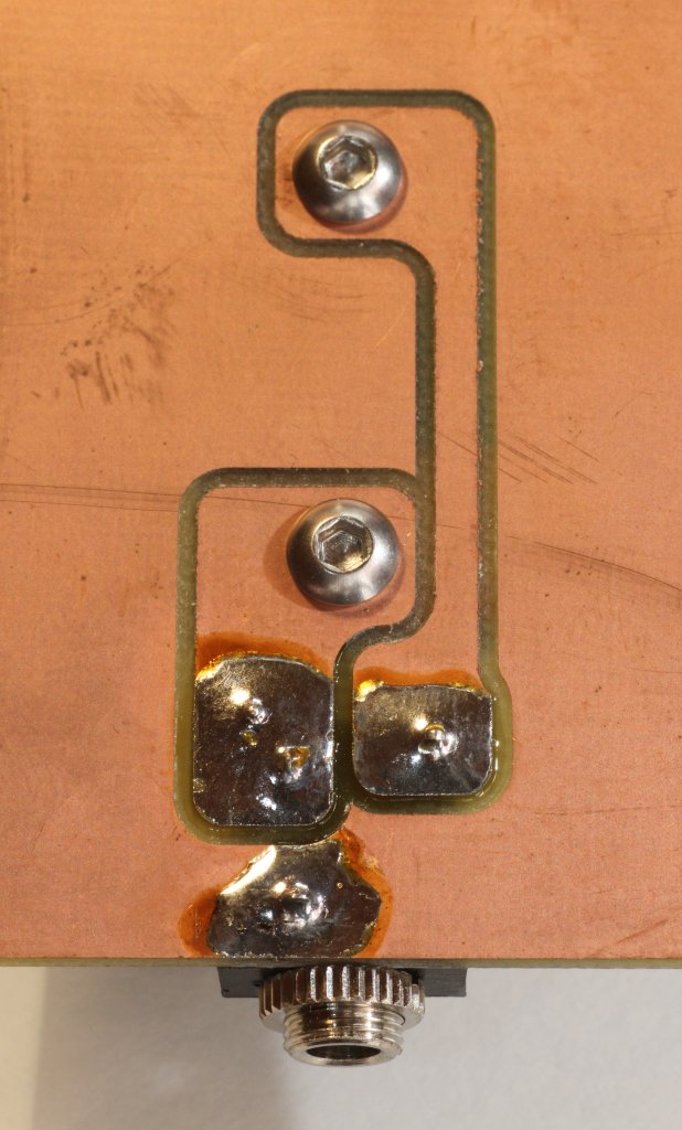
Closeup of the PCB tracks (click to enlarge).
This structure would be theoretically enough to send some CW code, but it proved to bee too light and not stable enough. To make the whole set heavier a 16 mm thick POM bottom plate has been added. Any other material like aluminium or hard wood will do the job as well. Just use a router to cut a slot in the middle allowing the screw heads to have enough clearance.
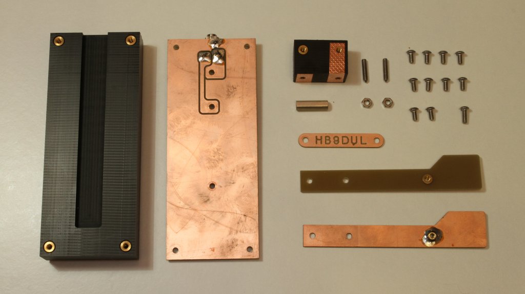
Disassembled view of all the components (click to enlarge).
On another piece of PCB I etched my call-sign that I installed in front of this key. One could also use double sided PCB for the base and etch the call-sign on the top layer. In any case, this is jest an esthetical detail.
This CW horizontal iambic paddle is a very simple yet effective construction, it uses very common materials and, with some mechanical skill, can also be quite a nice and good looking contraption to show to your friends. For sure, it's funny to build and to use. Even if it's not as good as a "true" commercial mechanical paddle, it's still fair and you can make real QSOs with it.
| Home | Mechanics | Page hits: 020044 | Created: 11.2013 | Last update: 11.2013 |