In this page a simple method of calculating mains frequency closed-core power transformers. This is intended for home brewing, repairing and modifying transformers. Please remark that even if this method and some equations could be generalized, only classical cores composed by steel plates are taken into account.
When designing a closed-core power supply transformer, the first step is to choose a suitable core according to the power the device will have to handle. Usually, for high power, large cores are required. Actually, there is no theoretical or physical reason preventing a small core from handling a large power, but for practical reasons, on a small core, there is not enough space to fit all the windings: a large core is the only choice. In order to choose a pretty good core right form the beginning, the following empirical formula (for a working frequency of 50 Hz) can help:

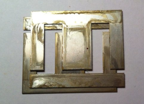
This equation links the (apparent) power P to the core cross-section surface A, taking into account core efficiency η (Greek "eta"). When measuring the core cross-section, one should remove about 5% in order to take into account the thickness of the varnish on the ferromagnetic plates composing the core. The cross-section A is the minimum cross-section of the magnetic circuit, usually measured where the windings are located as shown in the drawing below:
The above diagram shows a double-loop core, which is by far the most common type of core because of its low leakage flux and small size. It's called "double-loop" because the magnetic field generated by the coils in the middle of the core loops half on the left part of the core and half on the right part. In this case, it's important to measure the core cross section inside the windings (as shown), where the flux is not splitted in half. If your transformer is has a single magnetic loop, like a toroidal transformer, than the cross section is the same all around the core and it doesn't matter where you measure it.
The efficiency depends on the material composing the core; if not known, the table below will give a rough idea:
| Core plate material | Magnetic flux density φ [Wb/m2] |
Core efficiency η [1/1] |
| Grain-oriented silicon steel (C-shaped), M5 | 1.3 | 0.88 |
| Grain-oriented silicon steel (0.35 mm plates), M6 | 1.2 | 0.84 |
| Non grain-oriented silicon medium steel (0.5 mm plates), M7 | 1.1 | 0.82 |
| Non grain-oriented silicon standard steel (or for heavy duty) | 1.0 | 0.80 |
| Mild steel | 0.8 | 0.70 |
In order to simplify this operation, the following calculator can be handy:
This calculator already takes into account the 5% reduction of the core cross section.
Then, one has to determine the core flux density φ (Greek "phi"). Again, this depends on the material and, if not known, the same table will help. If the transformer is supposed to run continuously or in a poorly ventilated environment, slightly reducing the flux density (by 10%, for example) will reduce losses and keep the transformer cool at the cost of more iron and more copper. The opposite can be considered for reducing material cost in transformers only used for short periods of time, or not designed to run at full power continuously.
Once the flux density has been determined, one can calculate the transformer constant γ expressing number of turns per volt of all the windings, with the following formula:

The 106 factor takes into account that the core cross section is expressed in mm2. A few other things should be remarked about this formula: for example, low frequencies require more turns and you may have noticed that 60 Hz transformers that are usually a little smaller than equivalent 50 Hz ones. Than, a low flux density also requires more turns, meaning that to lower the flux in the core (and reduce losses) one have to wind more turns, even if this seems counterintuitive. The final remark is that large cores require few turns: if you ever looked inside huge high voltage transformers used by power companies for their high-voltage power lines, they only have few hundreds turns for many kilovolts, while the small 230 V transformer inside your alarm clock has thousands of turns.
Now that we know the transformer constant γ , it's easy to calculate the number of turns N for each winding with the formula:

Please remark that all voltages and currents are RMS values, while the flux density is expressed with its peak value to avoid saturation: this explains the √2 term in the equation of the transformer constant.
For secondary windings, it's a good practice to increase slightly the number of turns, say by 5% or so, to compensate losses in the transformer.
In order to simplify this operation, the following calculator can be handy:
This calculator already takes into account the 5% factor for the secondary turns.
You may have noticed, that the amount of turns depends on core size and flux density, but not on power. So, should your transformer require more than one secondary, simply repeat the calculation of windings for each secondary. But in this case, choose a core large enough to fit all the windings or, in other words, select the core size according to the total power of all the secondary windings. Also use a primary wire cross-section large enough to handle the total power.
The final step is to calculate the diameter of the wire for each winding. To do this, a conductor current density c has to be chosen. A good compromise is 2.5 A/mm2. A lower value will require more copper but generates fewer losses: it's suitable for heavy duty transformers. A higher value will require less copper and makes a cheaper transformer, but because of the increased heat, it will only be acceptable if used for short periods of time at full power or may require cooling. Common values are between 2 and 3 A/mm2. Once the current density is determined, the wire diameter can be calculated using the following equation:

Or, for c = 2.5 A/mm2:

In order to simplify this operation, the following calculator can be handy:
Now that the calculations are terminated, the hard part begins: will the calculated windings fit on the selected core? Well, the answer is not easy and depends on a large number of factors: wire cross-section and shape, wire bending radius, quality of the winding, presence of insulating foils between winding layers, and so on. On the other hand, some experience will be more helpful than plenty of equations.
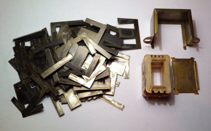
It's hard buy an empty transformer core, and usually home projects start from an old transformer to unwind and rebuild. Not all transformers can be disassembled: some are glued together with a resin that is too strong to remove without bending the core plates. Fortunately, many transformers can be disassembled by removing the cover that holds all the plates together or by grinding the two welds across all plates. Than, every plate has to be carefully removed in order to get access to the windings. Bent or scratched plates should be discarded.
With some luck, one can reuse the primary winding and rebuild only the secondary, unless the primary is winded over the secondary or has an unsuitable number of turns. When deciding if a winding should be kept as is or not, it's useful to determine its number of turns, but counting them is impossible without unwinding the coil. Fortunately, there is a trick to determine the number of turns: before disassembling the core, just wind a few turns (say 5 or so) of insulated wire around the windings and measure the voltage induced in this improvised secondary when powering the transformer normally. Form this value, it's easy to calculate the turns per Volt of the transformer and calculate the number of turns of every winding without actually counting them.
After the new windings have been winded, it's time to rebuild the core by putting all the plates back in place. Without a power press it will be hard to put back all of them, but if at the end one or two plates are left, the transformer will work fine anyway. But for this reason, one should slightly oversize the transformer when doing the calculations by selecting a smaller core cross-section. When the transformer is powered, the force on the core plates is significant and it's important to hold them tightly or to glue them; otherwise the core will vibrate and will be very noisy.
Many transformers have E-I core plates, like the one in the above picture. When rebuilding the core, the plates have to be crossed: E-I for one layer and I-E for the following one, and so on. This minimizes the air gap and helps keeping the coupling factor high.
Always use enameled copper wire for all the windings. PVC insulated wire (normal electric wire) is a very bad idea because the insulation layer is very thick, takes a lot of space in the core and is a very poor heat conductor: your transformer will very quickly overheat.
Always put a layer of insulating foil between primary and secondary windings if they are close to each other to prevent electrical shock hazard in case of wire insulation failure. Use something thin, that doesn't burn and that is a good insulator. I use Kapton tape, but regular electrical tape may work as well.
The insulation of enameled copper wire is usually good up to 1000 V (peak value). When available, have a look at the wire specifications provided by its manufacturer. If the voltage on a winging exceeds this value, it's better to split the winding into two or more layers separated by an insulating foil in-between.
A simple method of calculating mains power transformers has been presented and I hope this will help home brewers in designing their own transformers according to their specific needs. Winding our own transformers is often the only affordable choice when uncommon voltages are required. But disassembling a transformer, make new windings and putting it back together is a lot of work, so it's better to do some calculations before to get it right on the first attempt.
| Symbol | Description | Unit |
| A | Core cross-section | mm2 |
| d | Wire diameter | mm |
| f | Working frequency | Hz |
| I | Winding RMS current | A |
| N | Number of turns | 1/1 |
| P | Pransformer apparent power | VA |
| U | Winding RMS voltage | V |
| γ | Number of turns per V | turns/V |
| η | Core efficiency | 1/1 |
| φ | Core magnetic flux density | Wb/m2 |
Remark: 1 Wb/m2 = 1 T = 10'000 Gauss
| Home | Electronics | Page hits: 133919 | Created: 12.2011 | Last update: 12.2011 |