Modifications and improvements of the LX.1407 Geiger counter

Modifiche e migliorie al contatore Geiger LX.1407


Introduction

In June 1999 the Italian magazine Nuova Elettronica published an article about a Geiger counter [1]. They also sold it as a complete DIY kit that included the Geiger tube, the plastic box and the programmed microcontroller.

Remark: this pages refers to the above mentioned project. If you don't know it, you'll probably find very little interesting information here. If you're interested in building a Geiger counter, you should rather read this page.


Introduzione

Nel giugno del 1999 la rivista italiana Nuova Elettronica pubblicò un articolo su un contatore Geiger siglato LX.1407 [1] che vendeva come kit completo da montare, con tanto di tubo, di contenitore e di microcontrollore già programmato.

Nota: questa pagina fa riferimento al progetto di cui sopra e descrive come migliorarlo. Se non lo conoscete, quest'articolo vi sarà di poca utilità. Se invece cercate un progetto di contatore Geiger da costruire, vi consiglio piuttosto questo qui (solo in inglese, però).

The instrument before many modifications (January 2003) - Lo strumento prima della maggior parte delle modifiche (gennaio 2003) (click to zoom)
The instrument before many modifications with still its original silkscreen printed panel. The picture dates from January 2003. (click to enlarge).
Lo strumento prima della maggior parte delle modifiche con ancora il suo pannello serigrafato originale. La foto è datata gennaio 2003. (click per ingrandire).

At that time I was looking for a Geiger counter since the Chernobyl era and I was therefore very interested in that project. The price was fair and I decided to buy it and build it. The circuit worked fine with no apparent problem. But after having played with it for a while I discovered several design flaws that I corrected an improved over the years. I present here all the modifications I did explaining the details of what I did and why.

All'epoca, cercavo un contatore Geiger già dai tempi dell'incidente di Chernobyl. Così, visto che il circuito mi interessava ed il prezzo era corretto, decisi di acquistarlo e di montarlo. Il circuito elettronico funzionò subito senza problemi apparenti, ma dopo averlo usato per un po', mi accorsi che aveva diversi problemi che negli anni ho corretto e migliorato. Presento qui tutte le modifiche che ho fatto spiegandone nei dettagli il come e il perché.

Internal view of the instrument before many modifications (January 2003) - Vista interna dello strumento prima della maggior parte delle modifiche (gennaio 2003) (click to zoom)
Internal view of the instrument before many modifications (January 2003). The Geiger tube was already raised but the microcontroller was still the original one. The additional PCB (bottom left) was an RS-232 interface used to log the measurements on a PC; the new Arduino does that much better with its USB interface. (click to enlarge).
Vista interna dello strumento prima della maggior parte delle modifiche (gennaio 2003). Il tubo Geiger era già rialzato ma il microcontrollore era ancora l'originale. Il circuito stampato aggiunto (in basso a sinistra) era un'interfaccia RS-232 usata per registrare le misure su un PC; cosa permessa anche dal nuovo Arduino con la sua interfaccia USB che tra l'altro è più semplice da usare. (click per ingrandire).

In May 2007 Nuova Elettronica published another article [2] on that same project and an upgrade kit (LX.1407/B) to improve it and make it more accurate. I never tried this update, but it doesn't fix all the problems presented here and, if you want to do the same modifications I did, you won't need it.

Since this project is mainly known in Italy, I decided to present this page not only in English as the other pages of this site, but also in Italian. I hope this will be appreciated by those who have an LX.1407 and wish to modify it.

Nel maggio del 2007, Nuova Elettronica pubblicò un altro articolo [2] sullo stesso contatore Geiger presentando un kit siglato LX.1407/B per aggiornare lo strumento e migliorarne le caratteristiche. Pur non avendo mai provato quest'aggiornamento, non corregge tutti i problemi descritti in questa pagina, e se vorrete modificare lo strumento come ho fatto io, l'LX.1407/B non vi servirà.

Visto che questo kit è noto principalmente in Italia, ho deciso scrivere questa pagina non solo in inglese come il resto delle pagine di questo sito, ma di aggiungere anche una versione in italiano. Spero che questo sia di gradimento a chi possiede un LX.1407 e desidera modificarlo.


The position of the tube

The first modification is to cut a window in the box and move the Geiger tube so that radiations can reach it with minimum attenuation. I discovered that the plastic box that is one millimeter or so thick significantly attenuates the weak radiations we measure every day and the instrument is not very sensitive.

I discovered this phenomenon by chance, when I remarked different readings with the box open or closed. The instrument was indicating a slight increase of the readings only when the box was open. Through the closed plastic container, no difference could be detected. I thought that nuclear radiation would go undisturbed through thin layers of light materials like plastic, but it's not the case: the attenuation due to the plastic box is real and measurable.


La posizione del tubo

La prima modifica consiste nell'aprire una finestra nel contenitore e nello spostare il tubo Geiger affinché le radiazioni possano raggiungerlo indisturbate. In effetti, quel millimetro di plastica o poco più che compone la parete del mobile attenua in modo significativo le deboli radiazioni che incontriamo tutti i giorni e rende lo strumento poco sensibile.

Mi resi conto per caso di questo fenomeno, notando letture diverse con l'apparecchio aperto o chiuso. In effetti, lo strumento permetteva di rilevare un leggero aumento della lettura solo quando l'apparecchio era aperto. A traverso il contenitore plastico, nessuna differenza era misurabile. Pensavo che le radiazioni nucleari attraversassero indisturbate piccoli spessori di materiali leggeri come la plastica, ma non è così: l'attenuazione dovuta al mobile plastico è reale e misurabile.

Bottom view of the instrument -  Vista inferiore dello strumento (click to zoom)
Bottom view of the instrument. The Geiger tube is visible just behind the protection grid. (click to enlarge).
Vista inferiore dello strumento. Il tubo Geiger è visibile dietro la griglia di protezione. (click per ingrandire).

I cut open a window in the lower part of the enclosure and tried several materials to mechanical protect the tube while letting the radiation through. The tube is very delicate as its wall is only 50 μm thick and it must be handled with great care. At the end I choose a 10 mm galvanized steel grid made of Ø 0.8 mm wires because it gave the best results: it's rugged and protects well against mechanical chocks, but keeps the majority of the area clear so that the radiation is almost undisturbed. To mount it, on one side, I drilled a series of blind holes in the wall thickness, one every 10 mm. On the other side I clamped it in place with a small aluminum bar held by two screws.

Aprii quindi una finestra nel coperchio inferiore e provai diversi materiali per proteggere meccanicamente il tubo pur lasciando passare le radiazioni. Il tubo è molto fragile, lo spessore delle sue pareti è di soli 50 μm e va manipolato con molta cura. Alla fine scelsi una rete di acciaio zincato con maglia da 10 mm e filo Ø 0.8 mm che ha dato i migliori risultati: è robusta nel proteggere dagli urti e lascia passare la maggior parte delle radiazioni. Per fissarla, da una parte ho fatto una serie di fori ciechi nello spessore del mobile ogni 10 mm e dall'altra l'ho bloccata con una piattina d'alluminio tenuta da due viti.

The protection grid mounted to the lower cover - La griglia di protezione fissata al coperchio inferiore (click to zoom)
The protection grid mounted to the lower cover with a small aluminum bar and a couple of screws. The other side it's blocked in eight blind holes drilled in the thickness of the wall. (click to enlarge).
La griglia di protezione fissata al coperchio inferiore tramite una barretta di alluminio e due viti. L'altro lato è bloccato in otto fori ciechi nello spessore della parete. (click per ingrandire).

To move the tube closer to the window, I added to the original black plastic holders some additional metallic spacers of about 15 mm. The existing spacers are threaded M3.

Per avvicinare il tubo Geiger alla finestra, ho aggiunto delle colonnine metalliche ai due supporti di plastica nera esistenti per rialzarlo di circa 15 mm. I supporti esistenti sono filettati M3.

The Giger tube raised by about 15 mm - Il tubo Geiger rialzato di circa 15 mm (click to zoom)
The Giger tube raised by about 15 mm with two hexagonal and two cylindrical metal spacers. The black clips are the original ones supplied with the kit. (click to enlarge).
Il tubo Geiger rialzato di circa 15 mm con due colonnine metalliche esagonali e due cilindriche. I supporti in plastica nera sono quelli originali forniti nel kit. (click per ingrandire).

In their 2007 article [2], Nuova Elettronica proposed another good solution to this problem, consisting in moving the tube outside the container but inside a plastic cable conduit. The conduit protects the tube mechanically, but can easily be opened when needed. Since in 2007 my instrument was already modified, I decided keep my solution of the window with the grid.

Nell'articolo di maggio del 2007 [2], Nuova Elettronica propose una soluzione altrettanto buona che consiste nel montare il tubo all'esterno del mobile in una canalina di plastica. La canalina lo protegge meccanicamente, ma può essere aperta all'occorrenza. Siccome nel 2007 il mio strumento era già modificato, ho tenuto la mia soluzione.


Tube resistors

Since i was at it, I modified R5 from the original 10 MΩ to 4.7 MΩ which is much closer to the recommended value of the datasheet, that specifies 5 MΩ. This modification makes the tube a little faster in recovering after the detection of a pulse (dead time), but requires changing R1 as well, that has been reduced to 100 kΩ in order to keep the amplitude of the pulse.


Le resistenze del tubo

Ho approfittato per abbassare il valore di R5 da 10 MΩ a 4.7 MΩ perché il data-sheet del tubo specifica 5 MΩ come valore raccomandato. Questa modifica rende il tubo un po' più rapido nel recuperare dal tempo morto ma obbliga a cambiare anche il valore di R1 portandolo a 100 kΩ per mantenere invariata l'ampiezza dell'impulso.

Complete internal view of the instrument - Vista interna dello strumento completo (click to zoom)
Complete internal view of the instrument after all modifications. (click to enlarge).
Vista interna dello strumento completo con tutte le modifiche. (click per ingrandire).

The dead time is the time required by the tube to "process" the pulse when a particle is detected. If another particle arrives during this time, the tube won't see it. The SBM-20 (cyrillic СБМ-20) has a typical dead time of 190 μs at 400 V.

Il tempo morto, è il tempo che impiega il tubo a "trattare" un impulso. Durante questo tempo, se arriva un'altra radiazione, il tubo non la sente e resta "sordo". Il modello SBM-20 (СБМ-20 in cirillico) usato qui, ha un tempo morto tipico di 190 μs a 400 V.


The display

The biggest flaw of this circuit is that only three of the four digits on the display can be addressed by the microcontroller. The first digit can only be zero and only numbers in the form of "0.xxx" can be displayed. This always bothered me, because it limits what one can do by reprogramming or replacing the microcontroller. It's a pity, because the current display doesn't allow displaying high level of radiation or using a different measurement unit. After all, the cost of an additional CD.4094 won't have had a big impact on the cost of the instrument.


Il display

La più grossa lacuna di questo circuito era che solo tre delle quattro cifre del display erano pilotabili dal microcontrollore, la prima poteva solo essere zero, forzando a indicare solo numeri del tipo "0.xxx". Questo mi ha sempre disturbato, sin dall'inizio. Perchè limita drasticamente le modifiche che uno può fare riprogrammando o sostituendo il microcontrollore. Era un vero peccato, perché così com'era, non permetteva né di indicare livelli più alti di radioattività, né di cambiare unità di misura. In fondo, un CD.4094 supplementare non avrebbe inciso molto sul prezzo dello strumento.

The additional CD.4094 shift register - Il nuovo registro a scorrimento CD.4094 (click to zoom)
The additional CD.4094 shift register. It's mounted on an small piece of prototype board glued on the main PCB and connected with several thin insulated wires. (click to enlarge).
Il nuovo registro a scorrimento CD.4094. È montato su un pezzetto di piastrina millefori incollata al circuito stampato ed è collegato tramite molti fili isolati e sottili. (click per ingrandire).

So I decided to take a drastic measure and add the missing CD.4094 to independently drive all segments of the display. Actually, all segments but one: the colon (:) in the middle could not be connected as one additional CD.4094 was not enough. Since I didn't have any use for that, I didn't bother.

Ho quindi deciso di tagliare la testa al toro e di aggiungere il registro CD.4094 mancante per poter pilotare tutti i segmenti del display in modo indipendente. Per la precisione, tutti tranne uno: i due punti (:) centrali non ho potuto collegarli, perché sarebbe stato necessario ancora un altro CD.4094 e non avendone un'utilità immediata, ho lasciato perdere.

The display side of the PCB after all modification have been completed - Il lato display del circuito stampato a modifiche ultimate (click to zoom)
The display side of the PCB after all modification have been completed. (click to enlarge).
Il lato display del circuito stampato a modifiche ultimate. (click per ingrandire).

Modifying the actual circuit is a very fiddly and delicate job because the LCD display needs to be removed from its socket. It's made of glass and it breaks easily. I lifted it with great care using a small flat stick of wood to apply a uniform pressure under it. A pop stick works fine. Once the display is removed, the traces connecting pins 5, 6, 7, 8, 34, 35, 36 and 37 must be cut and connected to the new CD.4094. To install the new IC, I soldered it on a small piece of prototype board that I epoxied to the main PCB. Then, I connected the power supply of the new IC (pins 8, 15 and 16) and its four data lines (pins 1, 2, 3 and 9) by tapping into IC4.

Modificare il circuito è un lavoro delicato perché necessita la rimozione del display dal suo zoccolo: è di vetro e si spezza molto facilmente. Quindi ci vuole molta cura per sollevarlo, applicando una forza uniforme sotto di esso. Io ho usato un bastoncino di legno piatto come quelli usati nei ghiaccioli. Tolto il display, bisogna tagliare le piste facenti capo ai piedini 5, 6, 7, 8, 34, 35, 36 e 37, per poi collegarli al nuovo CD.4094 che ho saldato su di un pezzetto di piastrina millefori incollata con una goccia di resina epossidica su un lato del circuito stampato principale. Bisogna poi collegare l'alimentazione di questo circuito integrato (piedini 8, 15, e 16) e le quattro linee dati (pedini 1, 2, 3 e 9) prendendole, per esempio, da IC4.


Pulse width

In the original project, a one-shot circuit (IC1-B and IC1-C) was used to enlarge the pulses to about 2.5 ms. I don't really understand why this one-shot has been designed, as it's normally not required: a microcontroller that easily handle the 190 μs pulses provided by the tube. Furthermore this one-shot has the side effect of limiting the maximum count at about 20'000 cpm while an SBM-20 can measure 200'000 cpm or more. It has also the effect of increasing the dead time from 190 μs to 2.5 ms.

I therefore took the pulses directly from IC1-A output and I reused the one-shot circuit to drive an LED (see below).


La larghezza degli impulsi

Nel circuito originale, si utilizzava un monostabile composto da IC1-B e IC1-C per allargare gli impulsi a circa 2.5 ms. Non ho mai capito la necessità di questo monostabile, poiché un microcontrollore può gestire direttamente e senza problemi gli impulsi di circa 190 μs prodotti dal tubo. Inoltre, questo monostabile ha come effetto di limitare a circa 20'000 cpm la frequenza massima misurabile quando il tubo SBM-20 potrebbe produrre anche 200'000 cpm o più, e peggiora drasticamente il tempo morto facendolo passare da 190 μs a 2.5 ms.

Ho quindi prelevato il segnale per il conteggio degli impulsi direttamente dall'uscita di IC1-A ed ho riutilizzato il monostabile per pilotare un LED (vedi sotto).


Light and sound

I never liked the sound of the piezo speaker: it was driven by the microcontroller, it emitted a short "beep" at every pulse and sounded like a toy. Professional instruments, on the other hand, emit a "tick" sound, which is the typical sound of a Geiger counter, or, in other words, the sound that I wanted.

There was also an alarm function that I found very annoying because it could not be turned off, consisting of an acoustic signal for readings above 0.060 mR/h. Above that threshold, the instrument started beeping like an alarm clock and didn't produce the pulses of the radiations anymore.

Therefore, I deleted the oscillator that used to drive the piezo speaker CP1 by removing C3 and R4, but I kept IC1-D as a buffer to drive the piezo. I moved its input directly on the tube pulses (IC1-A output). The ticking sound is now very gratifying.

Now the speaker is directly connected to the pulses without going through the microcontroller. I initially planned to put a switch in series to mute the sound. But in the end, laziness won and I never installed this switch... I like the sound and I didn't want to modify the external look of the instrument by adding a different switch in some strange location.


Luce e suono

Il suono della cicalina non mi è mai piaciuto: nella versione originale era pilotata dal microcontrollore che gli faceva emettere un "bip" ad ogni impulso, facendo un suono da giocattolo. Gli strumenti professionali, invece, ad ogni impulso, emettono semplicemente un "tic" che è quello tipico dei contatori Geiger che conosciamo tutti, e questo è il suono che volevo.

C'era inoltre una funzione di allarme che non poteva essere disattivata. S'innescava a 0.060 mR/h ed era molto fastidiosa. In effetti, oltrepassata tale soglia, lo strumento si metteva a suonare come una sveglia e non permetteva più di sentire il ticchettio delle radiazioni.

Ho quindi eliminato l'oscillatore che pilotava la cicalina CP1 togliendo C3 e R4, e riutilizzato IC1-D come buffer invece che come oscillatore per pilotare la cicalina. Ho spostato il suo ingresso direttamente sugli impulsi (uscita di IC1-A) e il suono della cicalina è ora soddisfacente.

Visto che ora la cicalina è direttamente collegata agli impulsi senza più passare per il microcontrollore, avevo previsto di mettere un interruttore in serie ad essa per ammutolire il suono. La pigrizia però ha finito per vincere e non l'ho mai fatto... In fondo quel suono mi piace e non volevo rovinare l'estetica dell'apparecchio mettendo un interruttore diverso e lontano dagli altri.

Modifications of the display side of the PCB - Modifiche del lato display del circuito stampato (click to zoom)
Modifications of the display side of the PCB. Please remark the additional LED on the right of the display, the 22 kΩ resistor of the voltage divider (bottom left) and the diode in series with the power supply (bottom center). (click to enlarge).
Modifiche del lato display del circuito stampato. Si notino il LED aggiunto sulla destra del display, la resistenza da 22 kΩ del partitore di tensione (in basso a sinistra) e il diodo in serie all'alimentazione (in basso al centro). (click per ingrandire).

I also like to see an LED flash with the counted pulses. This function was missing in the original circuit. The pulses generated by the tube are too short to be seen if they drive an LED directly. It's necessary to enlarge them to a few milliseconds to see a bright flash. Since the one-shot circuit composed by IC1-B and IC1-C is no longer used, I took advantage of it to enlarge the pulses for the LED. The width is about 2.5 ms it's just right. No need to modify C2 or R3.

I installed the LED on a small piece of prototype board glued on the main PCB on the right of the LCD display. I than drilled a small corresponding hole in the case so that the LED can be seen from the outside.

Inoltre, a me piace vedere lampeggiare un LED al ritmo degli impulsi e questa funzione mancava al contatore originale. Ora, gli impulsi prodotti dal tubo sono troppo corti perché siano visibili se pilotano direttamente un LED ed è necessario allargarli a qualche millisecondo per poterli vedere. Siccome restava il monostabile composto da IC1-B e IC1-C ormai non più necessario per la misura, me ne sono servito per allargare gli impulsi e pilotare il LED. La larghezza è di circa 2.5 ms e fa proprio al caso nostro. Non è quindi stato necessario modificare né C2 né R3.

Ho montato il LED su pezzetto di piastrina millefori incollata su circuito stampato principale, su lato destro del display. Ho poi forato il mobile in corrispondenza in modo che sia visibile dall'esterno.


The microcontroller

The old microcontroller (to be more precise, the firmware running on it) had many problems that I describe below. But this IC, a ST.62T01, is now obsolete since a long time. So I replaced it with an Arduino Nano that I installed on the back panel with two angle brackets and a piece of prototype board. Even if the mechanical installation requires some work and that I had to connect it to the old IC2 location with 12 insulated wires, this configuration allows the Arduino USB connector to be easily accessible from the outside. Now the instrument can easily be connected to a PC for logging the measurements.


Il microcontrollore

Il vecchio microcontrollore (o più precisamente il firmware al suo interno) aveva tanti problemi, che descrivo qui sotto. Inoltre, questo microcontrollore, un ST.62T01, è ormai obsoleto da anni. Così l'ho sostituito con un Arduino Nano che ho montato sul pannello posteriore con due squadrette metalliche e un pezzetto di piastra millefori. È vero che il montaggio meccanico richiede un po' di lavoro e che ho dovuto collegarlo al vecchio zoccolo di IC2 con 12 fili flessibili isolati in plastica, ma questa configurazione ha il vantaggio di avere il connettore USB dell'Arduino accessibile dall'esterno e permette quindi di collegare il contatore Geiger ad un computer per poterne registrare le misure.

Connection of the new Arduino Nano microcontroller to the main PCB - Collegamenti del nuovo microcontrollore Arduino Nano al circuito stampato principale (click to zoom)
Connection of the new Arduino Nano microcontroller to the main PCB. Please remark the white wires connecting to the location of the old (removed) microcontroller and the yellow wires connecting the switches and the voltage divider. A ground terminal has been soldered to the ground plane at the position where the old crystal was; this allows an easy connection of an oscilloscope probe. (click to enlarge).
Collegamenti del nuovo microcontrollore Arduino Nano al circuito stampato principale. Si notino i fili bianchi che lo collegano alla posizione del vecchio microcontrollore e quelli gialli che collegano i pulsanti ed il partitore di tensione. Al posto del quarzo, è stato saldato un terminale alla pista di massa per poterci facilmente collegare la sonda di un oscilloscopio. (click per ingrandire).

The crystal XTAL and the two capacitors C4 and C5 are no longer used and I decided to remove them. And since I was at it, I also removed C14 since the Arduino board has its own bypass capacitors, even if I could have left these components in place.

Non essendo più utilizzati, ho smontato il quarzo XTAL e i condensatori C4 e C5. Poi, nella foga, ho smontato anche C14 visto che l'Arduino ha già i suoi condensatori di bypass, ma avrei anche potuto lasciarli.

The new Arduino Nano microcontroller mounted to the front panel - Il nuovo microcontrollore Arduino Nano fissato al pannello frontale (click to zoom)
The new Arduino Nano microcontroller mounted to the front panel. (click to enlarge).
Il nuovo microcontrollore Arduino Nano fissato al pannello frontale. (click per ingrandire).


The power supply

Powering the whole circuit with four AA 1.5 V alkaline cells is a solution that is probably a little old-fashioned, but works well and is extremely simple. I used it often in the past and I like the idea of not over-engineering the circuit. It's a good compromise for circuits like this, that draw little current and are not too critical on the stability of the 5 V rail.

But when you install four fresh batteries, the voltage can easily be over 6 V; still ok of regular C-MOS logic, but too much for a microcontroller. So, I added a 1N4148 diode in series to the battery, introducing about 0.6 V of voltage drop and therefore limiting the maximum voltage to 5.5-5.6 V and offering reverse voltage protection as well.

It has the disadvantage of lowering by 0.6 V also the minimum voltage the batteries can supply before being completely flat. It's the price to pay for using such a simple circuit, but in my opinion, this compromise is fair. A more complex power supply would cost much more than replacing the batteries slightly more frequently.


L'alimentazione

Alimentare direttamente tutto il circuito con quattro pile AA da 1.5 V è una soluzione che è forse un po' arcaica, ma funziona bene ed ha il merito di essere estremamente semplice. L'ho usata spesso in passato e mi piace il fatto di non complicare il circuito. È un buon compromesso per circuiti come questo che consumano poca corrente e che non richiedono particolare stabilita dell'alimentazione a 5 V.

Però quando si montano quattro pile nuove, la tensione può oltrepassare facilmente i 6 V; non è un problema per la logica C-MOS, ma è un po' troppo per un microcontrollore. Così ho aggiunto un diodo 1N4148 in serie alla pila che introduce una caduta di tensione di circa 0.6 V e limita la tensione massima a circa 5.5-5.6 V, oltre a proteggere il circuito in caso di inversione di polarità.

Ha lo svantaggio, però, di diminuire di 0.6 V anche la tensione minima che le pile possono fornire prima di essere completamente scariche. È il prezzo da pagare per usare un circuito semplice, ma il compromesso mi sembra accettabile, anche perché un'alimentazione più complessa costerebbe ben di più di qualche pila supplementare...

Inside view of the instrument - Vista interna dello strumento (click to zoom)
Inside view of the instrument. Please remark the additional CD.4094 integrated circuit (middle right) and the new Arduino Nano microcontroller (bottom right). (click to enlarge).
Vista interna dello strumento. Si notino il circuito integrato aggiunto CD.4094 (al centro a destra) e il nuovo microcontrollore Arduino Nano (in basso a destra). (click per ingrandire).

I chose to let the high voltage step-up circuit composed by TR1, TR2 and TR3 directly connected to the battery, before the diode. This will provide that additional 0.6 V that make it start easier when the battery are getting old.

For monitoring the battery voltage, I modified the original circuit that used an LM.336 regulator (IC3). I replaced it with a 22 kΩ resistor forming with the original R13 (3.3 kΩ) a 7.67:1 voltage divider. This allows to the new microcontroller to use its internal 1.1 V voltage reference.

Ho però scelto di lasciare il convertitore di alta tensione composto dai transistor TR1, TR2 e TR3 collegato direttamente alla pila, senza passare per il diodo. Questo gli permette di avere quegli 0.6 V in più che ne facilitano l'avvio quando le batterie cominciano ad essere un po' scariche.

Per misurare la tensione della pila, ho modificato il circuito originale che utilizzava un regolatore di tensione LM336 siglato IC3, sostituendolo con una resistenza da 22 kΩ. Questa, insieme a R13 da 3.3 kΩ forma un partitore si tensione con rapporto 7.67:1 e permette al nuovo microcontrollore di usare la tensione il riferimento interna di 1.1 V.


The buttons

To add additional features to the microcontroller, more buttons would be nice, but the space available between the PCB and the enclosure is very limited. Adding new buttons would not be esthetically nice, so I had to do a few compromises.

The power switch is unchanged: one is required anyway and the existing one was fine. The two push-buttons, "MAX" and "RESET" are still there, but their functions are now different and I labeled them "COUNT" and "TIME". Capacitors C15 and C16 that were in parallel to those switches to filter the bounces of the contacts are no longer needed and need to be removed; the software in the microcontroller does a better job.

I replaced the single pole double throw lever switch S1 with a single pole center off (triple throw) switch and I assigned it to a new function. This lever switch has the same dimensions and mechanical shape, but has three positions instead of two. This allows choosing the unit between mR/h, CPM or μSv/h. To install it, I had to cut a slot in the large ground plane on the PCB.

The original function of S1 was to mute the instrument removing the ticking of the piezo speaker. I initially planned to keep this function and add an extra switch in series with the speaker, but since there was no space on the front panel and that I didn't like the idea of a switch on a side, at the end I skipped this function completely. Finally, I kind of like this ticking sound and I never had the need to mute it.


I pulsanti

Per aggiungere nuove funzioni al microcontrollore servirebbero più pulsanti, ma lo spazio tra il circuito stampato e il mobile è molto limitato. Aggiungere bottoni non sarebbe stato esteticamente gradevole, così ho dovuto fare qualche compromesso.

L'interruttore di alimentazione è rimasto tale e quale; infondo, uno è necessario e andava bene così. I due pulsanti, "MAX" e "RESET" sono rimasti, ma le loro funzioni sono ora differenti e li ho ribattezzati "COUNT" e "TIME". I condensatori C15 e C16 che erano in parallelo ai pulsanti per filtrarne i rimbalzi non sono più necessari e vanno rimossi; il software nel microcontrollore li gestisce senza problemi.

Ho sostituito però l'interruttore S1 che era usato per ammutolire la cicalina con un deviatore a levetta a tre posizioni cambiandone la funzione. Questo ha la stessa forma esterna, ma ha tre posizioni invece di due. Queste permettono adesso di scegliere l'unità di misura tra mR/h, CPM o μSv/h. Per farlo, però ho dovuto tagliare il largo piano di massa sul circuito stampato.

La funzione originale di S1 era quella ammutolire lo strumento togliendo il ticchettio della cicalina. Inizialmente avevo previsto di mantenere questa funzione e di aggiungere un interruttore supplementare in serie ad essa, ma non potendolo mettere sul pannello frontale per ragioni di spazio, e non trovando esteticamente gradevole di metterlo si un lato, alla fine non l'ho messo. In fondo, il ticchettio mi piace non lo spengo mai.


The final circuit diagram

The final circuit diagram is visible below. The original unmodified portion of the circuit diagram is represented in black, while modifications are in blue. For clarity, removed components or connections are not shown here.


Lo schema elettrico finale

Trovate nella figura qui sotto lo schema elettrico finale con tutte le modifiche. Il circuito originale non modificato è in nero mentre le modifiche sono in blu. Per avere un disegno più chiaro, i componenti e le connessioni rimossi non sono rappresentati.

Final circuit diagram - Schema elettrico finale (click to zoom)
Final circuit diagram. Modifications are in blue. Removed components from the original circuits are no longer represented here, see text. (click to enlarge).
Schema elettrico finale. Le modifiche sono disegnate in blu. I componenti eliminati dal circuito originale non sono rappresentati, vedi testo. (click per ingrandire).


The problems of the old firmware

The biggest problem of the old firmware was the conversion factor used to compute the exposure in mR/h. Readings were two to three times lower than what was measured with other instruments and this is what pushed me to rewrite a completely new firmware.

By connecting the old microcontroller to a signal generator, I could determine that the factor used was 4'000 cpm per 1 mR/h, while the SBM-20 tube requires 1'530 cpm per 1 mR/h. You can find here how I determined and verified this value.

With the signal generator I could also find that when the frequency of the pulses increases above 3000 cpm (50 Hz), the microcontroller started to loose pulses. The higher the frequency, the more lost counts. I'm glad that I never used this instrument with highly radioactive levels; otherwise it would have produced wrong and misleading readings. Such a problem could not be tolerated in an instrument.

Furthermore, the microcontroller firmware froze from time to time when the pulse frequency was high. At every freeze a general reset was necessary to resume readings. This problem could not be tolerated neither.

To be sure that the new microcontroller handled all the pulses correctly, once all the modification were completed, I connected again the signal generator to verify its performance up to 600'000 cpm (10 kHz), which is about twice the frequency the tube can theoretically provide.


I problemi del vecchio firmware

Il più grosso problema del vecchio firmware è il fattore di conversione usato per calcolare l'esposizione in mR/h, ed è anche quello che mi ha spinto a rifare completamente un firmware, perché le misure erano due o tre volte inferiori a quanto rilevato da altri apparecchi.

Collegando il vecchio microcontrollore ad un generatore di segnali, ho potuto stabilire che la conversione usata era 4'000 cpm per 1 mR/h quando il tubo SBM-20 necessita un valore di 1'530 cpm per 1 mR/h. Trovate qui (solo in inglese, però) come ho potuto stabilire questo valore e come ho potuto verificarne l'esattezza.

Con il generatore di segnali ho anche potuto stabilire che all'aumentare della frequenza, a partire da circa 3'000 impulsi al minuto (50 Hz) il microcontrollore perdeva impulsi, e più la frequenza saliva, meno contava. Per fortuna non ho mai avuto a che fare con livelli di radioattività elevati, ma se fosse successo, lo strumento avrebbe fornito misure errate e forvianti. Un tale difetto non poteva assolutamente essere tollerato.

Inoltre, il microcontrollore aveva tendenza a bloccarsi con frequenze d'impulsi elevate; tanto più spesso che la frequenza era alta, necessitando a ogni bloccaggio di un reset generale per riprendere il funzionamento. Anche questo problema non poteva essere tollerato.

Per essere sicuro che il nuovo microcontrollore gestisca correttamente tutti gli impulsi, a lavoro ultimato, ho ricollegato il generatore di segnali per verificarne il funzionamento fino a 600'000 cpm (10 kHz) che è una frequenza di circa due volte più elevata di quella che il tubo teoricamente può fornire.


The new firmware

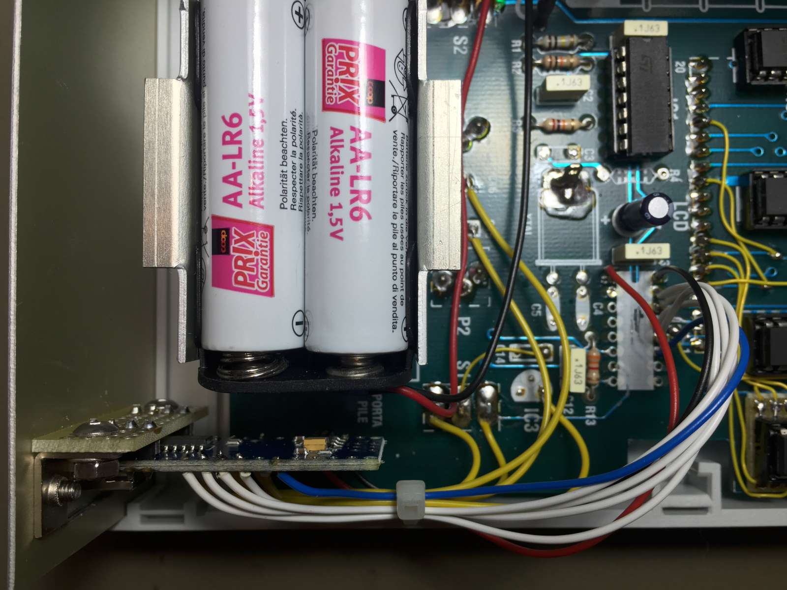
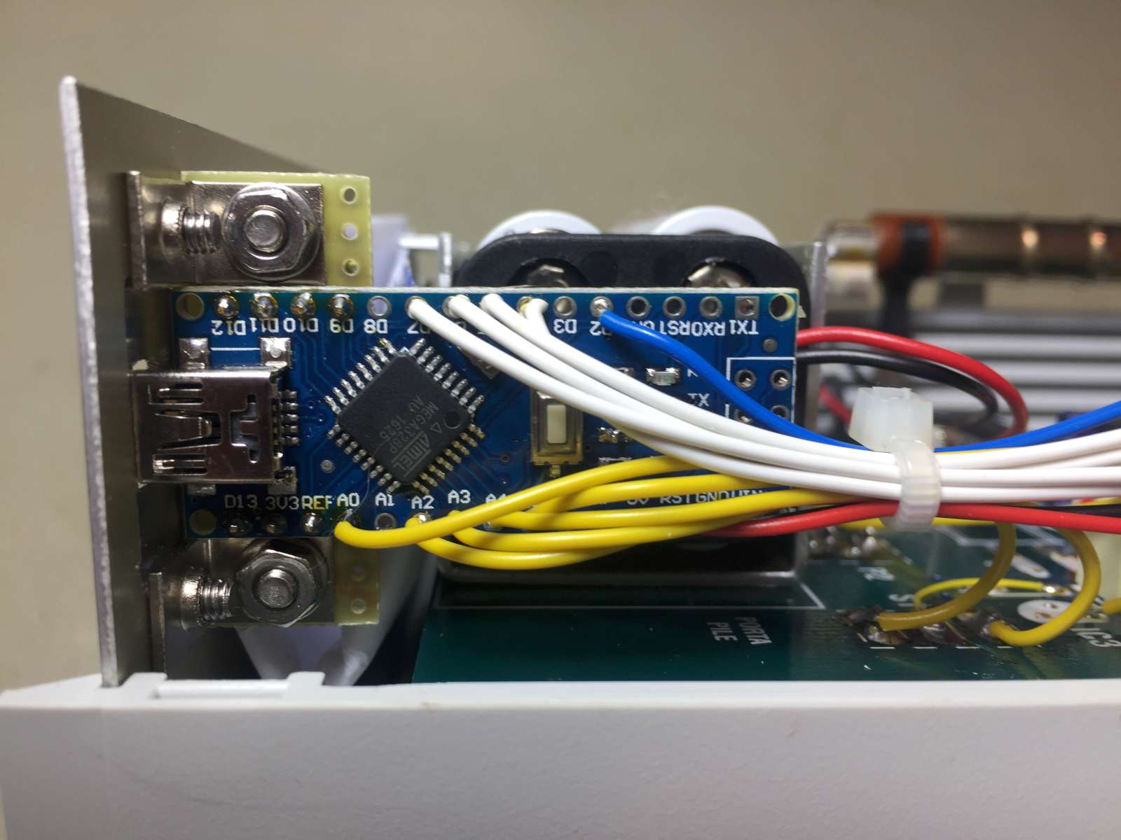
Replacing the old microcontroller with an Arduino Nano was the easiest thing to do. Also because I could reuse many parts of the code I already wrote for the twin-tube counter.

So, with little effort I could have the dead-time compensation, the PC communication interface, the conversion from CPM to mR/h and μSv/h, the low voltage alarm, and so on.

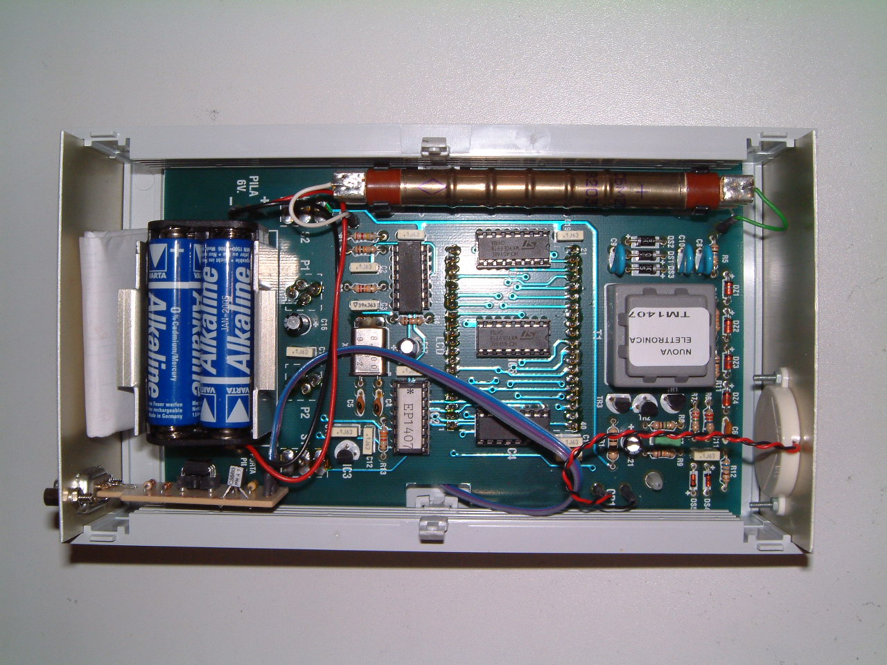
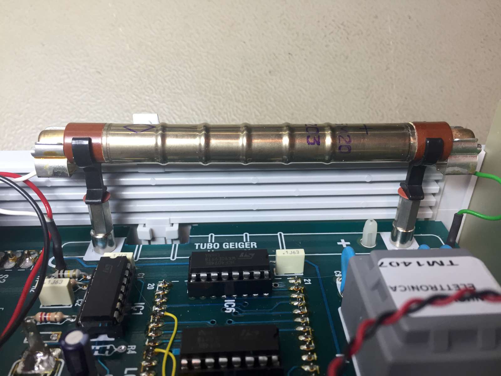
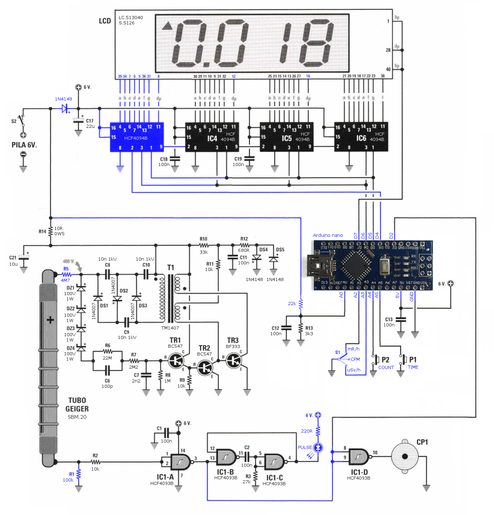
Pulses generated by the tube are shaped by IC1-A and arrive on line D2. This line internally supports interrupt capabilities (INT0) and allows counting all the pulses (falling edge) regardless of what the processor is doing.

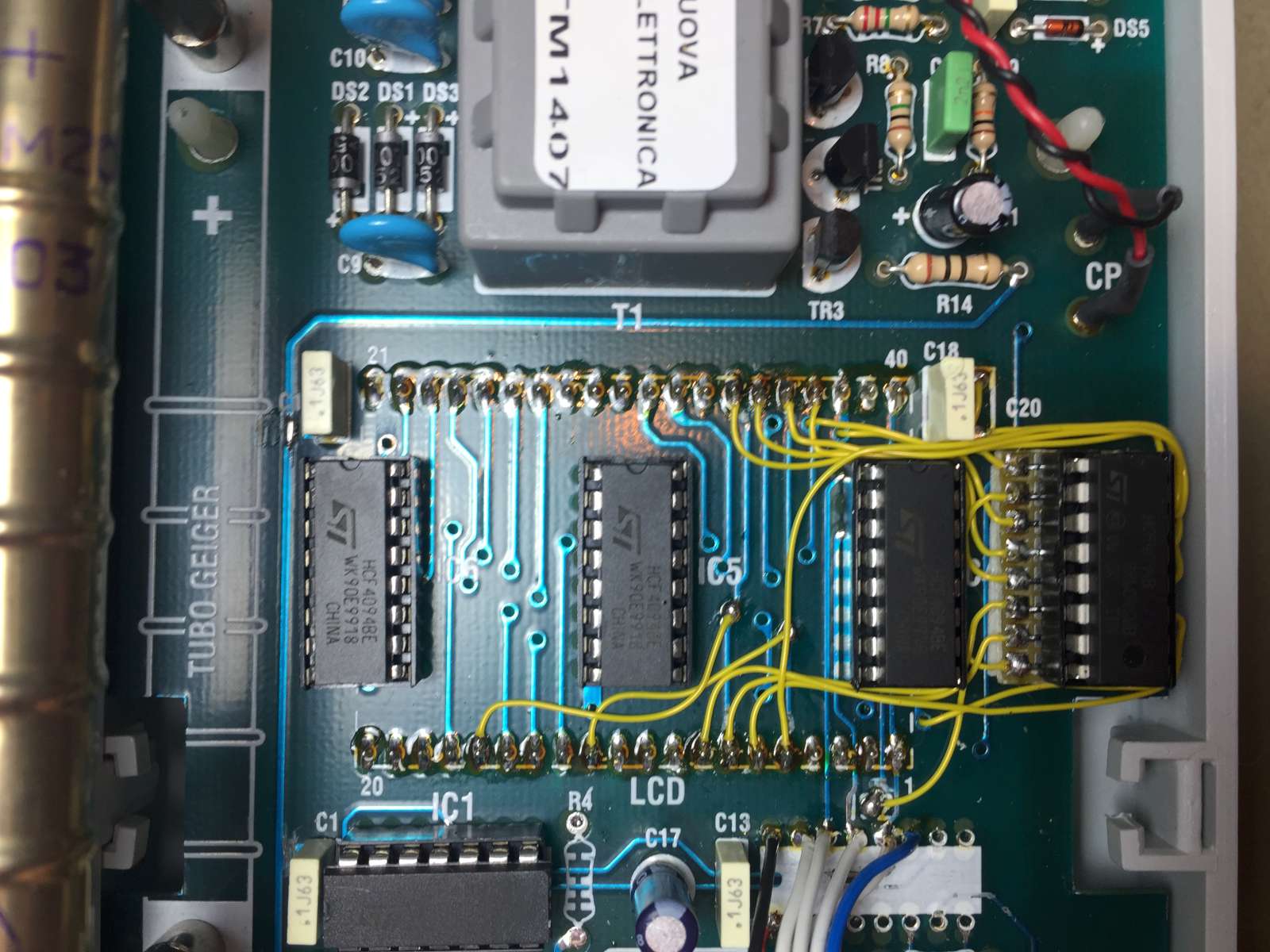
The LC513040 LCD display must be AC driven to avoid harmful electrolysis phenomena in the liquid crystals. Its data-sheet specifies that the frequency must be between 30 and 200 Hz. I choose to drive it at 50 Hz by programming the microcontroller to rewrite the four CD4094 100 times per second and invert all outputs each time.

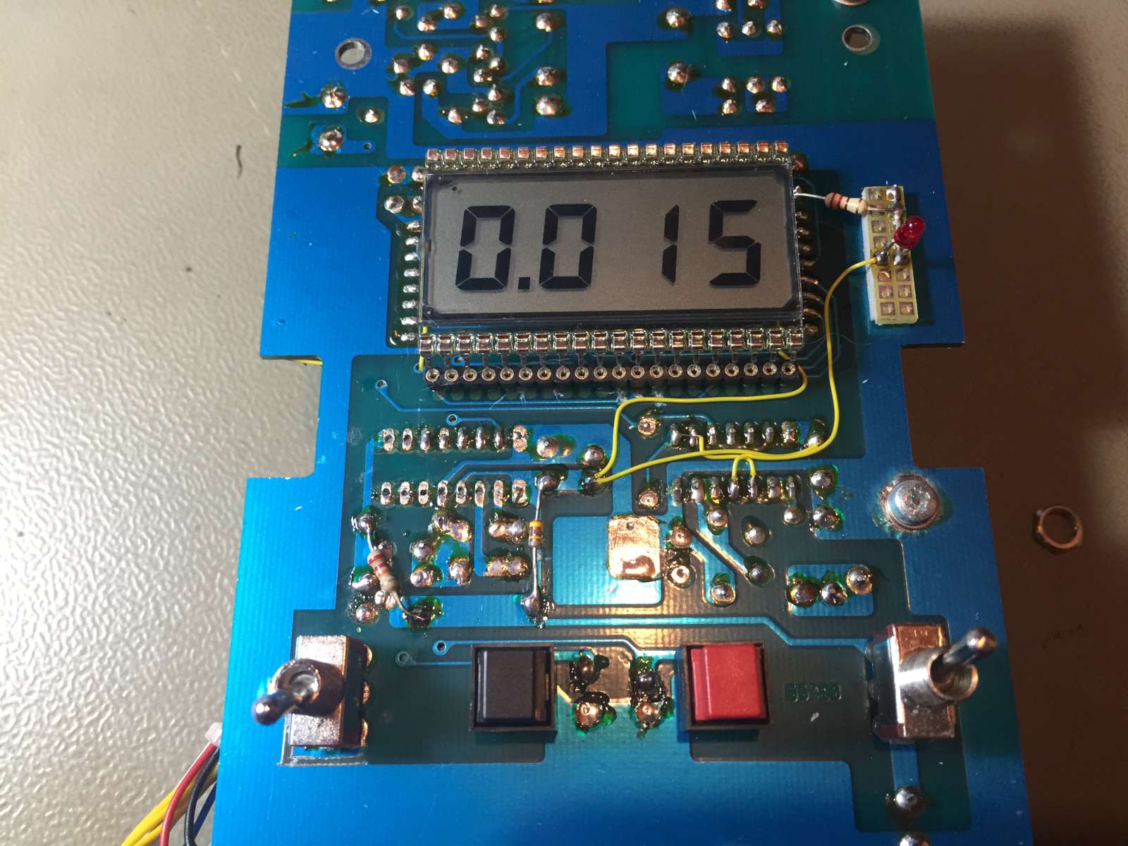
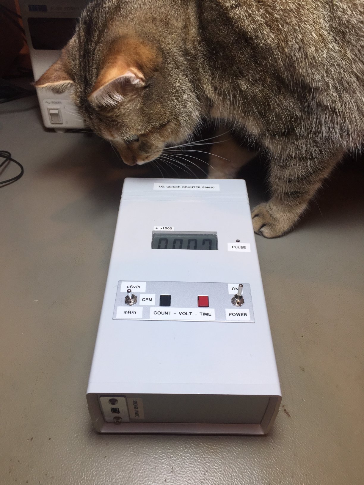
To fit large numbers on the four digit display, when the value exceeds 9'999, it's divided by 1'000, the decimal point is shifted accordingly and a little triangle in the top left corner will tell the user about the extra 1'000 factor. So, for example, "^15.67" actually means 15'670.

The firmware (program) used for this application is available here (as freeware): lx1407-firmware.zip (19,704 bytes).


Il nuovo firmware

Sostituire il vecchio microcontrollore con un Arduino Nano era la cosa più semplice da fare, anche perché mi ha permesso di riutilizzare una buona parte del codice che avevo già scritto per il contatore a due tubi.

Questo ha permesso di implementare con poco sforzo la compensazione del tempo morto, l'interfaccia di comunicazione con il PC, la conversione in CPM, mR/h e μSv/h, la gestione della batteria scarica, e via dicendo.

Gli impulsi provenienti dal tubo, debitamente squadrati da IC1-A arrivano sulla linea D2 che internamente supporta la funzione di interrupt INT0 e permette di conteggiare tutti gli impulsi (fronte discendente) indipendentemente da ciò che il processore sta facendo.

Il display LCD tipo LC513040 deve essere pilotato in corrente alternata per evitare dannosi fenomeni di elettrolisi nei cristalli liquidi. Il data-sheet specifica che la frequenza deve essere compresa tra 30 e 200 Hz. Io ho scelto di pilotarlo a 50 Hz, facendo in modo che il microcontrollore riprogrammi i quattro registri CD4094 100 volte al secondo ed invertendo ogni volta i valori di tutte le uscite.

Per indicare numeri grandi sul display a quattro cifre, quando il valore oltrepassa 9'999, questo viene diviso per 1'000, la virgola viene spostata e un triangolino in alto a sinistra indica il fattore 1'000. Così, per esempio, "^15.67" significa 15'670.

Il firmware (programma) usato in questa applicazione può essere scaricato qui (freeware): lx1407-firmware.zip (19,704 bytes).


Features and how to use the new firmware

The instrument is controlled with two buttons and a switch (and a power switch, but its function is trivial). The switch has three positions, is connected to D16/A2 and D17/A3 and allows selecting between mR/h, μSv/h and cpm. Holding button P2 (connected to D18/A4) shows the actual number of pulses counted in the current period. Holding button P1 (connected to D19/A5) will show how many seconds are left until the end of the current integration period. Pressing and holding both buttons together will show the battery voltage. Battery voltage is sampled via a voltage divider on pin D14/A0.

Integration period is fixed and set to 10 seconds. It can be changed by pressing and holding P1 or P2 while switching the power on until the new time is displayed on the screen. P1 will set the integration time to 60 seconds for long and precise measurements of low radioactive levels and P2 to 2 seconds for quick measurements of strong levels.


Funzioni e utilizzo del nuovo firmware

Il contatore dispone di due pulsanti e un deviatore a levetta a tre posizioni (e un interruttore di alimentazione, ma il suo funzionamento è ovvio). Con il deviatore che fa capo alle linee D16 e D17 si può scegliere l'unità di misura da usare per i risultati tra mR/h, μSv/h e CPM. Tenendo premuto P2 (facente capo a D18) vien mostrato il conteggio attuale degli impulsi mentre tenendo premuto P1 (facente capo a D19) viene mostrato il tempo restante fino alla fine della misura attuale. Tenendo premuti entrambi i bottoni, viene invece mostrata la tensione della batteria in Volt, che viene letta tramite un partitore resistivo e la linea A0/D14.

Il tempo d'integrazione di ogni misura à fissato a 10 secondi. Può però essere cambiato tenendo premuto P1 o P2 all'accensione dello strumento. P1 permetterà un tempo di 60 secondi per misure lunghe e precise di livelli di radioattività deboli e P2 permetterà un tempo di 2 secondi per misure rapide di livelli elevati.

Top view of the instrument - Vista superiore dello strumento (click to zoom)
Top view of the instrument. Please remark the additional LED on the right of the display. (click to enlarge).
Vista superiore dello strumento. Si noti il LED aggiunto sulla destra del display. (click per ingrandire).

Each time an integration period ends, the display is updated and the raw measurements are also echoed on the USB serial port at 9600 bps. No calculation in mR/h nor μSv/h is done on the serial communication, as this can easily be done by the remote PC, based on the raw data. Tube conversion constants and data format is transmitted at boot time. As a reminder, the SBM-20 tube produces 175 cpm at 1 μSv/h and 1'530 cpm at 1 mR/h. Dead time is 190 μs at 400 V.

If the battery voltage drops below 4.5 V a "bAtt" message flashes on the screen, but the readings are still visible between the flashes.

Alla fine di ogni periodo di integrazione il display viene aggiornato e le misure grezze vengono inviate sulla porta seriale USB a 9600 bps. Per la comunicazione, non viene effettuata nessuna conversione in mR/h o μSv/h, visto che questa può essere effettuata facilmente con un PC a partire dai dati grezzi. Le costanti di conversione del tubo e il formato dei dati vengo trasmessi una volta ad ogni accensione dell'apparecchio. Per memoria, il tubo SBM-20 genera 175 cpm a 1 μSv/h e 1'530 cpm a 1 mR/h. Il tempo morto è di 190 μs a 400 V.

Quando la tensione della batteria scende al disotto di 4.5 V la scritta "bAtt" lampeggia sul display, ma la misura può ancora essere letta tra due lampeggi.


Conclusion

In this page I describe the modifications I did to my LX.1407 Geiger counter to improve it and make it more sensitive. Since I'm satisfied with the new performance, I decided to share them here, hoping that they may be of some interest to anybody owning an LX.1407 and wanting to tune it up a bit.


Conclusione

In questa pagina ho presentato le modifiche che ho fatto al mio contatore Geiger LX.1407 per migliorarlo e renderlo più sensibile. Visto che ne sono rimasto soddisfatto ho deciso di pubblicarle, sperando che possano interessare a chi, come me, possiede un LX.1407 e desidera migliorarlo un po'.

No... my cat is not radioactive... - No... il mio gatto non è radioattivo... (click to zoom)
No... my cat is not radioactive... (click to enlarge).
No... il mio gatto non è radioattivo... (click per ingrandire).


Bibliography


Bibliografia

[1] LX.1407 – Un nuovo ed efficiente contatore Geiger. Nuova Elettronica, Anno 31, Numero 200, Giugno/Luglio 1999, Pagina 2.
[2] Per i lettori che hanno aquistato il contatore Geiger LX.1407. Nuova Elettronica, Anno 39, Numero 230, Maggio 2007, Pagina 114.