This document describes a simple SWR-meter suitable for long and medium waves bands (137 and 500 kHz). The design is nothing new and very similar to common short wave meters, but it has been designed to work with low frequencies.
The majority of amateur radio SWR-meters are specified for short waves or higher frequency and it's very hard to find an instrument suitable for 137 or 500 kHz use. Many are rated 1.8 to 54 MHz, some can span from 1.8 to 150 MHz, but I never found a commercial meter specified below 1.8 MHz. Of course, professional equipment like a Bird directional watt-meter can do the job, but this page is about "cheap" amateur meters.
The first idea is trying available meters to see if the can do the job below 1.8 MHz even if they are not designed for, but the results are very disappointing since none of the ones I had on hand worked at 137 kHz. The test is very simple: just connect your long-waves transmitter to a suitable 50 Ω dummy load via the SWR-meter under test and look at the reflected power: if you gat a non-zero reading, your meter is not suitable for long waves.
Being below the minimum specified working frequency of the instrument, one could tolerate some percent of error in the absolute power readings. But the fact that the reflected power is not zero when connecting a dummy load cannot be accepted at all, because it will be impossible to match the antenna with such an instrument.
The large majority of amateur SWR-meters are bridge circuits based on current transformers (at least those designed for frequencies up and including short waves). Current transformers are limited in the upper end of the band by their stray capacitance and by the length of the wire composing the windings. In the lower end they are limited by the inductance of the windings: if this inductance isn't large enough, a significant phase error will result, the bridge will be out of balance and the measurements will be wrong.
In order to get the transformers to work at low frequency, the inductance of the secondary winding has to be large enough: let's say, as a rule of thumb, that its impedance should be at least ten times larger than the terminating impedance (usually 50 Ω). Increasing the number of turns on the transformer will also increase the stray capacitance and increase the overall length of the wire; as a consequence the maximum working frequency will also decrease, but this is acceptable since we are designing an instrument for long waves.
For the winding stray capacitance, we should make sure that the self resonance of the winding should be well above the highest desired working frequency. We should also make sure that the length of the wire doesn't exceed one tenth of the shortest wavelength.
To have a high inductance with only a few turns (and a short wire) we have to choose a magnetic core with a high AL value. Ferrite cores can have high AL values, powdered iron cores usually do not.
Once these conditions are met, the same usual bridge circuits will work on the desired band.
Many SWR bridge circuits are available and well known, the most popular being the Bruene's bridge. All of them can be made to work on long-waves and the selection of a circuit has a lot to do with personal choices. There are bridges with one, two or three transformers; some have transformers with two secondary windings, some use capacitive dividers, some others use resistors, many have RC or RL networks for frequency compensation.
In order to keep the design as simple as possible, a "tandem match coupler" (also known as "Sontheimer bridge") has been selected, mainly because it uses two identical transformers, it doesn't require trimmer capacitor adjustments for its frequency response and is very simple to build. The schematic diagram is visible in the figure below.
As usual, the "dots" represent the beginning of each winding and show the way the different windings are correctly (in phase) connected together. The four resistors load the coupler outputs with 50 Ω and make sure the bridge is balanced. Make sure these resistors are not (too much) inductive.
The selected bridge uses two identical transformers. The transformer ratio has is set to 1:25: this will divide down the voltage (and the current) by 25 ensuring reasonable voltage even with a power of 1 kW as shown in the table below:
| Input power |
Input RMS voltage |
Input peak voltage |
Divided peak voltage |
| 10 W | 22 V | 32 V | 1.3 V |
| 100 W | 71 V | 100 V | 4.0 V |
| 1000 W | 220 V | 320 V | 13 V |
The Ferroxcube TN25/15/10-3F3 toroidal ferrite core was selected, mainly because it was available in the junk box. This core has an AL of 1.84 μH, a μ of 1800, has an external diameter of 25.8 mm, an internal diameter of 14 mm and is 10.6 mm high. It's important to use a core with a high AL and a high μ in order to get enough inductance with 25 turns. Any similar core will work.
The primary winding is composed by just one turn, which is quite usual in this kind of transformer. The secondary has therefore 25 turns, and with this particular kind of core it has an inductance of 1.1 mH, ensuring that the reactance will be above 500 Ω (ten times the load impedance of 50 Ω) starting at about 75 kHz.
The secondary winding requires about 1 m of wire, meaning that the transformer should be usable up to about 30 MHz if we want to keep this length shorter than one tenth of the wavelength. On the other hand, the stray capacitance limits the maximum usable frequency to a few megahertz: more than enough for 137 and 500 kHz.
Since the working frequency is low and that the primary to secondary stray capacitance is low as well, it has been decided not to shield the primary winding as it's usually done for higher frequencies.
In order to display the measurements a very simple passive circuit has been used and it can be seen in the figure below:
First the two RF signals are rectified by two germanium diodes D1 and D5 and than the signals are averaged in the two capacitors C1 and C2. Because of the 25:1 transformer ratio, the voltage on the diodes will be fairly low even with a high input power: a 50 V rated diode would work fine for 1 kW. Germanium diodes can be replaced with small signal Schottky diodes (BAT43 or similar, for example), and by loosing some low power sensitivity, even silicon diodes (like 1N4148) can do the job.
The power range switch SW1-SW2 is connected in an unusual way: it's because it's not a true double-pole tripe-thread switch but a double-pole double-thread lever switch with an additional center off position.
A double ammeter that was originally a VU-meter in a stereo amplifier was used as display instrument. A cross-needle instrument would be much fancier, but they are almost impossible to find. In any case, knowing directly the exact SWR is not really important, as we tune our antennas for the minimum possible reflected power and we can get away with two separate meters. The six silicon 1N4148 diodes are there to protect the meters by clamping the voltage if a too small power range is accidentally selected.
In order to see the reading at night a backlight with three white LEDs has been added following the following diagram:
The two 100 nF capacitors are just there to short circuit to ground any RF energy that may be coupled inside the instrument and avoid the external power cable to radiate. Except for the backlight, this SWR-meter requires no external power.
Building this SWR-meter is quite simple. It all starts from a suitable metal box. Since I didn't have one on hand I quickly built a small box with a scrap copper sheet, but aluminum is fine (and cheaper) as well. Keeping the RF connections short and making good ground connections is always a good idea, but in this case frequencies are low and connections are not very critical.
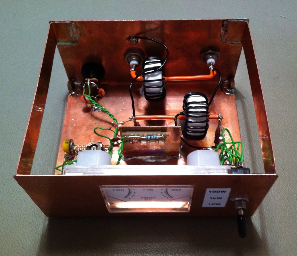
There is no need for a PCB and a piece of proto-board will be enough to mount the trimmers. The rest can be wired "in the air".
The power shown by the meter is not linear since the meter displays a rectified voltage while the power is proportional to the square of the voltage. The scale has therefore to be redrawn in order to get a direct reading. The figure below shows the final scale used in this instrument:
VU-meters like the one used here are not linear instruments as well, so the scale was experimentally determined by varying the transmitter power and by measuring the voltage on the dummy load with an oscilloscope (applying P = (Upeak-peak)2/(8R) ).
For another version of this SWR-meter using two different ammeters, the following scales were designed, and this time the meters are precise 100 μA linear instruments:
For adjusting the trimmers, one has to connect the transmitter to a suitable 50 Ω dummy load via this SWR-meter. First adjust the output power to a low value, ideally 10 W, select the 10 W meter range and switch the transmitter on. The "reflected" meter should read zero; if not something is wrong in the value of R3, R4, R8, R9 or the two transformers are not connected in phase. Now adjust R1 to match the reading of the "forward" meter with the applied output power (the meter should read 10 W in this example). Than select the 1 kW power range, adjust the output power of your transmitter to a higher value, ideally 1 kW, and adjust R2 for a 1 kW reading. Now select the 100 W range, readjust your transmitter for a lower power, like 100 W, and adjust R5. When this is done, swap the load and transmitter connections on the SWR-meter and start again: this time the "forward" meter should read zero and do the same adjustments to R6, R7 and R10 to calibrate the "reverse" meter.
The full schematic is available here: lw-swr-meter.pdf (31,399 bytes).
A simple SWR-meter suitable for long-waves use has been described. It's very similar to regular SWR-meters used for short-waves but the high inductance of the transformers secondary winding allows operation on low frequencies.
| Home | Electronics | Page hits: 064870 | Created: 01.2012 | Last update: 01.2012 |