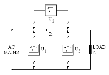
Connections of the three voltmeters and the additional resistor.
Measuring the power factor (also called cos φ) is something that we often need to do when dealing with AC mains circuits. Ideally, every load connected to the mains supply should have a cos(φ) of 1, but many devices like electric motors or old fluorescent tube ballasts are inductive and have a lower power factor. To correct the power factor, usually a capacitor of suitable value is connected in parallel. But to verify that the capacitor effectively corrects the power factor, there is no other way around than measuring it.
It must be said that the opposite situation, even if not very frequent, is also possible: an AC load could have a low power factor due to its capacitance that could be fixed by adding an inductor. Again, measuring the power factor is the only way to make sure we did a good job.
If you are reading this page, I assume it's because you need to measure the power factor, and in this case you already know what it is. If not, I try to briefly explain it here.
In a DC circuit, the power dissipated by a load is just its current I multiplied by the voltage U across its terminals: P = U·I. For AC powered circuits, it's a bit more complex: voltage and current vary with time and so does the power. In other words the instantaneous power is always the product of the instantaneous voltage and the instantaneous current, so we we have p(t) = u(t)·i(t). But this is not practical, because the instantaneous power p(t) varies with time: to have a comparable "steady" power P as we are used in DC, p(t) is averaged out over a full AC cycle.
Now, depending on the actual nature of u(t) and i(t) the resulting power P may vary. Let's limit ourselves to linear circuits (composed only by resistors, inductors and capacitors) and sinusoidal waveforms, as usual in AC circuits, so that we can take some shortcuts and simplify the math. Here, to calculate the (active) power, the equation is a bit more complex: P = U·I·cos(φ), where cos(φ) is the power factor and φ is the phase angle between voltage and current.
Simply multiplying the voltage by the current as we are used to do in DC circuit gives the apparent power S = U·I. It's called apparent because it doesn't correspond to a useful power that the load can use, it's just obtained by multiplying U and I. To stress the difference between active power P and apparent power S, the first is measured in Watts (W) and the second is measured in Volt-Ampères (VA), reminding how it was calculated.
For example, if the load is a pure resistor, voltage and current are perfectly in phase, φ = 0°, cos(φ) = 1 and we can simply calculate P = U·I as we are used to do with DC circuits. This is how all loads connected on the mains should be.
If the load is a perfect capacitor, the current always leads the voltage by φ = –90° and cos(φ) = 0: this means the power, averaged on one full cycle, is zero. That's ok, because capacitors dissipate no power. But now we have P = 0, even if U and I are both nonzero. Here, the term "apparent" power deserves all its meaning: it looks like there is power delivered to the load, S = U·I is not zero, but because of the phase difference (power factor), P is zero! The same is true for a prefect inductor, where φ = +90°, but cos(φ) = 0 and P = 0 as before.
Real loads are never perfect inductors or capacitors, but a mix of resistance with capacitance or inductance. In any case, φ is between –90° and +90°, while cos(φ) is always between 0 and 1. It's worth mentioning that the power factor cos(φ) is always between 0 and 1, no matter if the angle φ is negative (capacitive load) or positive (inductive load).
Please remark that to compute power, U and I must be expressed in their RMS (root mean square) value and not their peak value.
Power factor meters exist, but are difficult to find and are hardly ever available on the home-brewer workbench. Even if you have an oscilloscope, it's still a tricky measurement to do: oscilloscopes are internally grounded and cannot be directly connected to the AC mains; floating the oscilloscope with an isolation transformer is a dangerous operation, since the scope chassis will be at mains potential. Then, the majority of the oscilloscopes do not withstand the direct mains voltage on their inputs and special high-voltage probes are required. On the other hand, if all these problems can be solved, measuring the angle φ with an oscilloscope is very accurate.
Fortunately, there is a very simple trick to measure cos(φ) called the three voltmeters method: you just need three AC voltmeters and a resistor. But in practice, you don't really need three voltmeters: you can get by with just one, and very often it's better to only use one.
The downside is that it only works fine for linear loads such as motors or transformers; it also works quite well with some sligthly nonlinear loads like inductive fluorescent tube ballasts or transformer based arc welders, but doesn't work with strongly nonlinear loads such as rectifiers (basically any electronic ballast, switching power supply, motor driven by frequency converters,...).
The idea is simple: just connect a resistor R in series with the load and measure the three voltages U1, U2 and U3 as shown in this diagram:
Connections of the three voltmeters and the additional resistor.
Once you have measured the three voltages U1, U2 and U3, simply use the following equation to directly calculate the power factor:
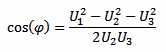
The actual value of R is not required for calculating the power factor, the voltage drop U2 across it is all you need.
The right choice of the resistor is crucial. To find out the best value of R, you have to balance two aspects: accuracy and voltage drop. You want a resistor large enough so that your voltmeter (or multimeter) can measure it with enough accuracy; but not too large, otherwise the voltage available to the load will be too small.
The voltage of the mains supply is usually guaranteed to be within ±5% of its nominal value (and sometimes even ±10%): losing a few volts across R is often not an issue. And many multimeters tend to be quite inaccurate when measuring small AC voltages (at least the cheap ones) so, I think 5 to 10 V across this resistor is reasonable.
The resistor must handle the power (P = U22/R) without overheating, at least for all the time it takes to do the measurements, so use a part rated accordingly.
You also want a resistor which is not inductive, but this is usually not a problem at 50 or 60 Hz, where inductances like 100 μH can often be neglected.
High power resistors can be expensive or hard to find, but this method doesn't require a precise value of R: with some creativity you can probably find a suitable part in your junk box. For example, a filament light bulb may be a solution: it's not inductive and some models can handle a lot of power. Light bulbs are non-linear resistors as their value changes with current, but if your load is steady, they can be used. Other examples are resistive heating elements, like electric water boilers, kettles, toasters,... they all have high-power resistors inside, maybe you can find what you need in your kitchen.
Now, a few words about using three voltmeters at the same time or just one and measure the three voltages one after the other. We will see later that this method determines an angle by measuring three sides of a triangle, two very long sides (U1 and U3) and a very short one (U2). If one or two of the measurements are off, this will introduce a significant error in the angle. On the other hand, if all measurements are off by the same percentage, all errors will cancel out and the angle will be right. So, unless you have three accurate and well calibrated instruments, it's much better to use the same one to measure the three voltages. Test your instruments before taking the measurements, this will save you a lot of time!
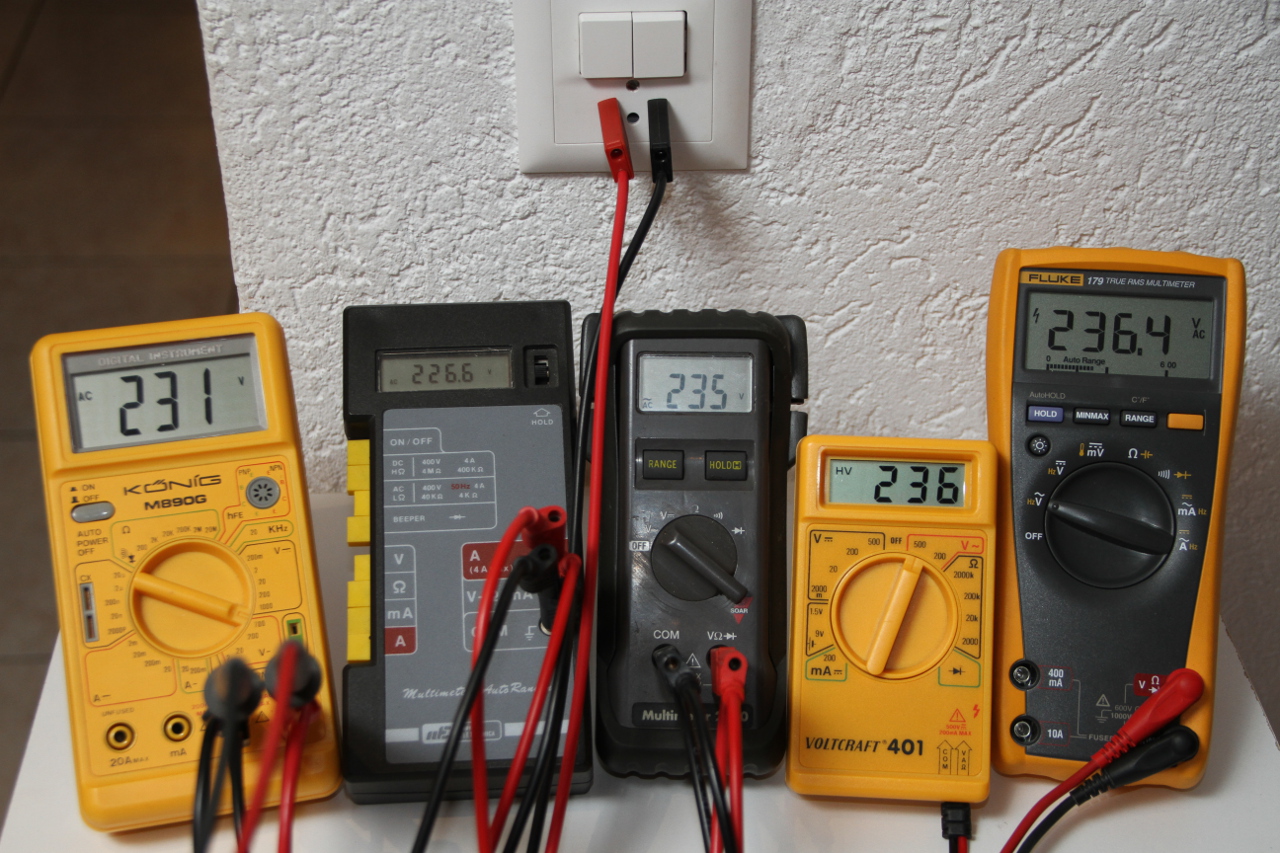
Five multimeters reading the mains voltage: they don't all agree on
the same value.
It's a good idea to verify your instruments first. (click to enlarge).
But using only one voltmeter has some downsides: first the mains voltage is often unstable. If it changes while you're doing your measurements, it will introduce errors. For this, you can try doing your measurements at night when there are less variations. Monitoring the mains voltage with an additional instrument (even if not accurate) can be a good idea: it will show you how stable the voltage is, and if you see it changing too much, just redo all three measurements (after all it doesn't take very long).
Second, if your load is not constant but changes over time, you will have a hard time with just one voltmeter. In this case you would need three good and calibrated multimeters, but if you don't already have them, it's probably cheaper to buy a power factor meter...
The following calculator will do the maths for you: just enter the three voltages U1, U2 and U3, and hit the "calculate" button to find cos φ.
If you also enter the value of the resistance R (optional), this calculator will compute the line current I apparent power S and the active power P.
(*): Optional value.
The final formula looks very simple, and you may be wondering why this works. So, let's consider the circuit once again:
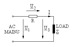
Schematic diagram of the circuit. Underlined letters are phasors.
The vector sum of U2 and U3 is, of course U1 and since R is a pure resistor, the current I is perfectly in phase with voltage U2, as summarized in the phasor diagram below:
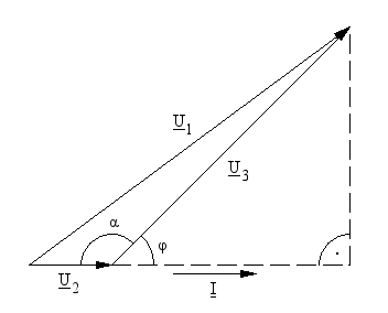
Phasor diagram of the three voltages U1,
U2 and U3 and their
relation with the angles α and φ.
The angle we are looking for is φ, between load current I and load voltage U3, while α is the angle between U2 and U3. Using the law of cosines and considering only the magnitudes of the phasors, we can write:
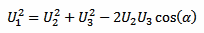
Which is just the relation between the three sides U1, U2 and U3 of the triangle and the angle α.
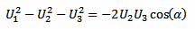
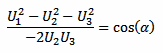
Now we can rearrange a little bit and solve for cos(α):
From our phasor diagram above, we have that:

Substituting and using the property cos(180° – x) = –cos(x), we can now solve for cos(φ):
And finally we have:
In the calculator above, if the value of R is given, the load current is calculated with:

Which allows calculating the apparent power with:

And, since we just found the power factor cos(φ), also the active power can easily be calculated with:
To further illustrate this method, let's have a look at a few examples. Even if I usually only use one multimeter because I don't have three good quality reliable multimeters and because using the same instrument three times is more accurate, here I borrowed some trustful instruments so that I could have all the readings in the same picture.
The first example is the induction motor of a bench grinder, nominally rated 230 VAC, 50 Hz, 250 W. For the series resistor, I used an array of seven power resistors mounted on a heat-sink for a total of 8.15 Ω - 150 W that I usually use as dummy load for testing audio amplifiers. As you can see in the picture below, U1 = 239.5 V, U2 = 4.630 V and U3 = 235.7 V.
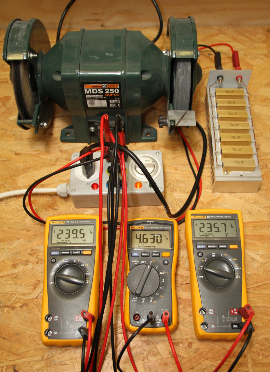
A bench grinder being measured with the three voltmeters method.
The three multimeters show, from left to right, U1,
U2 and U3.
The resistor (top right) is rated 8.15 Ω - 150 W.
(click to enlarge).
By putting all these values in the calculator, we find the power factor cos(φ) = 0.82, the current I = 0.57 A, the apparent power S = 134 VA and the active power P = 110 W. It's not a surprise that this motor is using less than half its nominal power, because it's turning idle and it's just compensating its own losses. Power consumption will go up when grinding something.
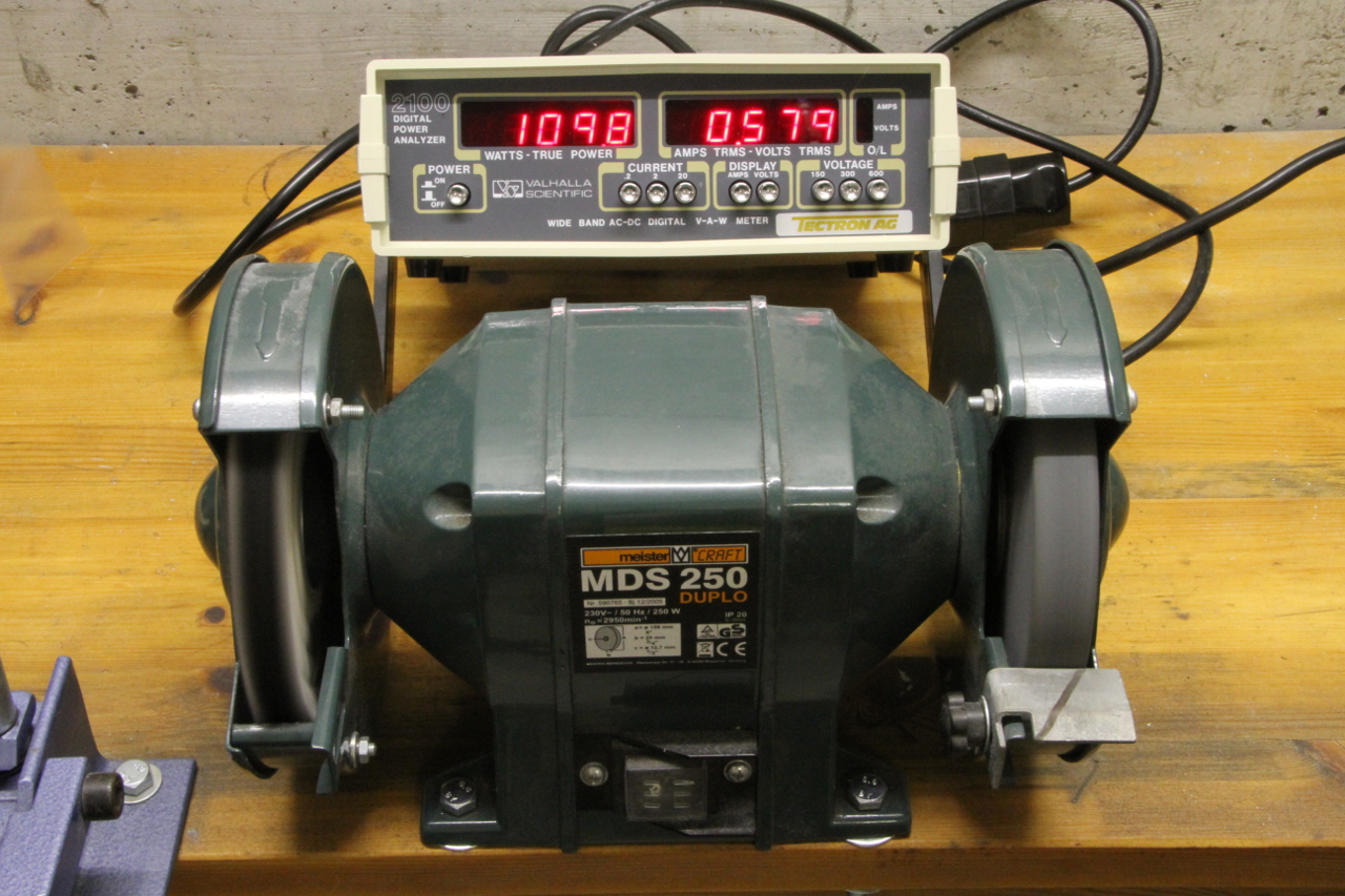
The same bench grinder being measured with an AC power analyzer.
(click to enlarge).
To verify this three voltmeters measurements and calculation, the same bench grinder is measured again with an AC power analyzer: it reads 109.8 W and 0.579 mA, well confirming our result (the accuracy of all the instruments used here is not better than ±1%).
The second example is a big halogen lamp transformer, rated 220 VAC, 50-60 Hz, 400 VA, with no load connected to its secondary (a transformer with no load is usually quite inductive). Here, because the transformer has no load and uses a much lower power, the series resistor is 165 Ω, 17 W. As you can see in the picture below, U1 = 239.7 V, U2 = 11.10 V and U3 = 232.9 V.
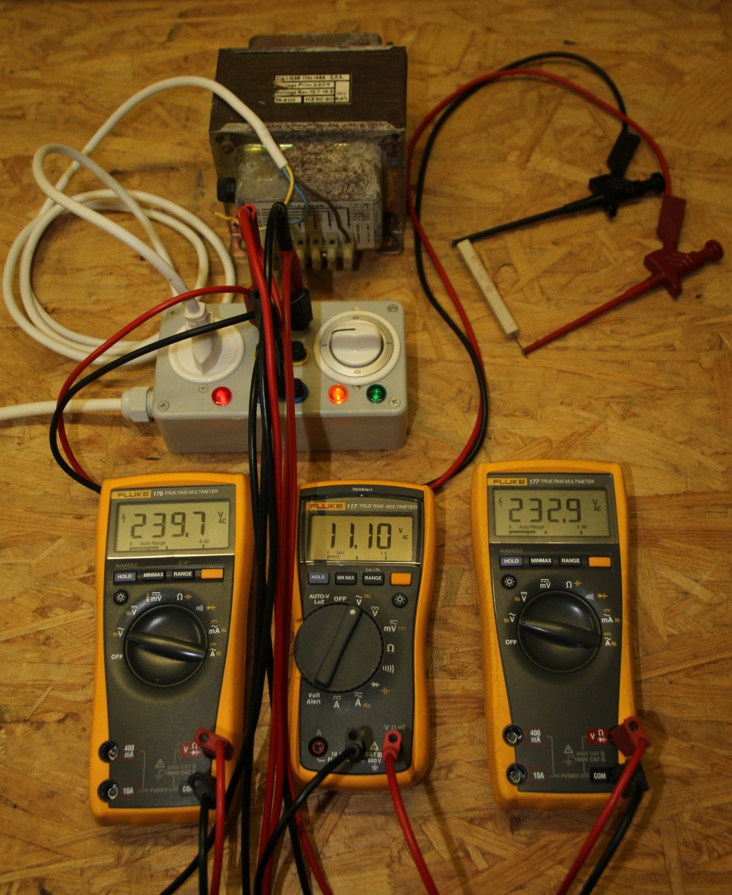
A transformer (without load) being measured with the three voltmeters
method.
The three multimeters show, from left to right, U1,
U2 and U3.
The resistor (top right) is rated 165 Ω - 17 W.
(click to enlarge).
By putting all these values in the calculator, we find the power factor cos(φ) = 0.60, the current I = 67 mA, the apparent power S = 16 VA and the active power P = 9.4 W.
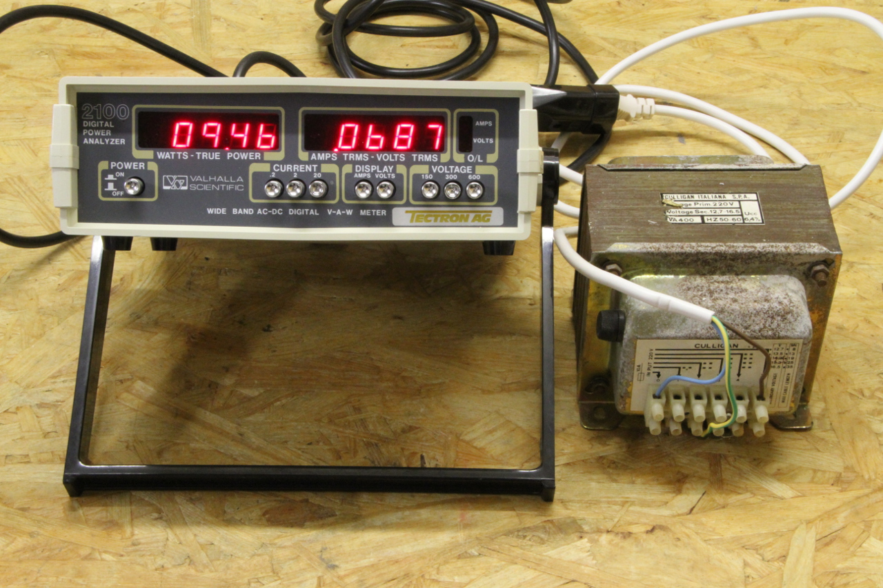
The same transformer (without load) being measured with an AC power
analyzer. (click to enlarge).
Measuring the active power with an AC power meter gives 9.46 W and 68.7 mA, confirming again our calculation.
If you wonder what's in the gray box, it's just a mains outlet with a double pole switch and three jumpers. It allows interrupting any of the three AC wires for measuring the current or inserting a resistor while using regular insulated 4 mm banana plugs. This prevents exposing too many live parts or having poor contacts that may burn or spark if the current is high enough.
The "three voltmeters method" of determining the power factor is an attractive alternative to the home experimenter with limited equipment. It's not as easy to use as a true power analyzer and not as precise as an oscilloscope (properly equipped for high voltage measurements), but requires only a multimeter and a resistor. I hope this will be helpful in many situations where dedicated instruments are not available.
| [1] | Wolfgang Link, DL8FI. Metodi di misura per radioamatori. Franco Muzzio & C. editore, 1978, sezione 8.1.3. |
| Home | Electronics | Page hits: 108988 | Created: 11.2014 | Last update: 02.2021 |