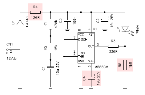
Circuit diagram of one oscillator. Components highlighted in red have been added afterwards to fix the problems.
A few years ago, I found in my junk-box a few dozen LM555CM chips in nice SO-8 SMD packages. Considering that the 555 is more than 40 years old (it was first introduced by Signetics in 1971) and is largely obsolete, I started thinking of a nice way of using all of them, since there are very little chances that I will ever need more than one or two in the next twenty years. So, I decided to use 38 of these ICs to make a flashing Christmas decoration. The idea was to build independent 38 oscillators that will flash LEDs at a slightly different frequency so that the flashes appear somehow random and have a "shiny" effect.
This project was far too easy to deserve a place in these pages: the circuit diagram is so simple that it doesn't need any description as 555 circuits are widely known and documented in the last four decades and I thought there was nothing interesting in it. But after building it I stepped into an interesting problem that made me change my mind: in spite that all oscillators are independent and have a slightly different frequency when tested alone, connecting a few of them on the same power supply, makes them synchronize after a few minutes and operate all at the same frequency and in synch!
Circuit diagram of one oscillator. Components highlighted in red have been added afterwards to fix the problems.
Let's start with the schematic diagram of one oscillator and let's ignore the components highlighted in red (R4, R5 and C4). There are 38 identical oscillators like this one connected in parallel to the same 12 VDC power supply. R1, R2 and C1 set the operating frequency and duty cycle. With 470 kΩ, 15 kΩ and 10 μF the LED is on (output low) for 0.1 seconds and is off (output high) for 3.4 seconds. C1 is a tantalum capacitor and as all capacitors of this kind has a large tolerance on its value (something like ±20%) ensuring that all 38 oscillators will have different operating frequencies. R3 sets the current in the LED at about 25 mA providing a nice bright flash on a white LED.
So fa far so good, each oscillator individually works fine and has a different operating frequency. But after connecting several of them in parallel things get interesting. Each oscillator starts with its own frequency, but after a while, say a dozen flashes, the majority of them blinks in perfect synchronism and only a few resist at their own frequency. After an hour or so, all oscillators are synchronized. The only possible coupling is via the power supply, so the first thing is connecting an oscilloscope on the power supply and look at the voltage: it looks pretty stable and clean, it only drops a few millivolts each time a LED is turned on. I wish I had a screenshot of the scope trace, but unfortunately I don't. Capacitors C2 and C3 were part of the initial design.
To understand why all oscillators want to synchronize with each other, it must be said that the 555 IC works by monitoring the voltage on capacitor C1 against a threshold voltage. When the output (pin 3) is high (LED off), C1 is charging via R1 and R2 in series. The output will turn low as soon as the voltage on pin 6 rises above two thirds of the supply voltage. This threshold voltage is generated with an internal resistor divider. If the power supply voltage drops by a few millivolts, the threshold voltage also drops proportionally. The voltage on C1 is not affected much by this variation as R1, R2 and C1 act as a low-pass filter and smooth out the glitches. So, if an oscillator is about to flash, but not quite yet, a slight drop in the supply voltage will change the threshold and make it flash immediately. Since all oscillators have similar frequencies, after several cycles they are all in sync, with the faster one forcing the other to flash at the same time.
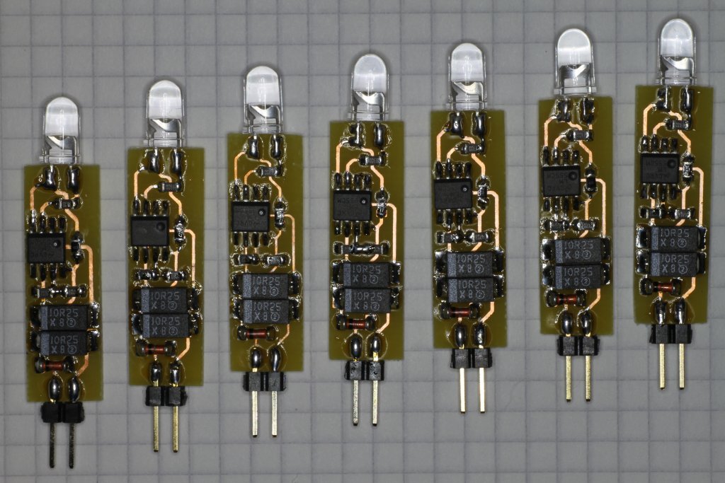
Seven oscillators before the modification. The grid on the paper is 4 mm. (Click to enlarge).
To solve this issue I first tried to add a single and very large 10'000 μF capacitor in parallel with the power supply, but it didn't help: glitches on the power supply were still present. Then I added resistor R4: it improved the situation quite a bit. Its role is to force the flashing LED in using the energy stored in C2 first and not to draw directly from the power supply. C2 has than plenty of time to recharge while the LED is off. Then I added C4 to directly filter the threshold voltage (pin 5); alone it wasn't enough, but greatly improved the situation. This capacitor is often omitted when using a 555, but strongly suggested in the datasheet: here it's really useful. Both R4 and C2 are needed to completely fix the problem and prevent the oscillators from synching together. Finally, there was no need for the bulky 10'000 μF capacitor on the power supply and it was removed.
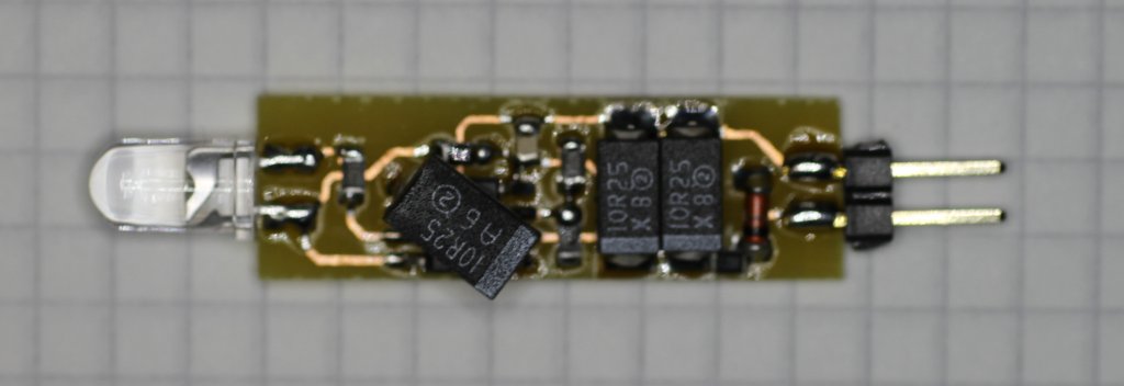
An oscillator after adding R4, R5 and C4 (click to enlarge).
Surprisingly enough, I couldn't find on the internet a suitable comet shape to finish this project, but I was finally inspired from a cookie mold my wife has in a drawer... So I cut a piece of 4 mm plywood with the same shape (but much larger), I drilled 38 Ø 5 mm holes for the white LEDs, fixed all the oscillators in place with hot glue, and hanged it at one of my windows.

Front view of the comet light (click to enlarge).
I was quite happy with the result, but a final problem appeared: when observed in complete darkness, the shape of the comet was not visible as the LEDs are completely off when not flashing. So, I decided to add an extra resistor R5 to keep the LED slightly glowing when off and make sure you can see them in compete darkness.
You may think that choosing a value for R5 is an easy task, but it turned out to be quite critical. If the resistor is too small, the LED draws the expected current, but doesn't glow; if it's too large, it's just too bright. With the LED I have, the best value is 1.8 kΩ, knowing that with 2.2 kΩ they almost don't glow at all and that with 1.5 kΩ they are already too bright. With 1.8 kΩ the idle current is about 4.7 mA. If you have different LEDs, you may need to pick (experimentally) a different value for R5.

Back view of the comet light (click to enlarge).
The following short video shows the effect of these 38 blinkers first in ambient light and then in a more dark environment.
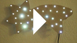
Watch the movie: cometflasher.mp4
(3,183,559 bytes, 11 s, H264, 960 × 540, 25 fps).
A very simple Christmas gadget has been presented. It's a very old fashioned circuit and there is no rocket science. I decided to describe it in these pages only because of the synchronization problem, that I think is of some interest; the rest of the circuit is pretty boring. If I didn't have all these 555 ICs laying around, I would most probably have used a microcontroller for its many advantages: using less components, being cheaper, being more flexible and never having the synchronization problem...
| Home | Electronics | Page hits: 008491 | Created: 12.2015 | Last update: 12.2015 |