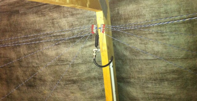
Picture of the feedpoint of my multi-dipole antenna.
A few years ago, right after moving in my new QTH, I decided to build a multi-band multi-dipole antenna in the attic, just to be discrete and not to have troubles with my neighbors. Within the dimensions of the attic, the antenna could cover the 20 m, 17 m, 15 m, 12 m and 10 m bands. Unfortunately, at that time I only had an SWR-meter and a grid-dip meter at hand and I quickly realized that tuning a multi-dipole antenna with only these instruments it's not easy. I remarked that the antenna had more resonances that expected and that they weren't very sharp, but I couldn't manage to get all the resonances exactly in all the bands, but the integrated antenna tuner of my TX took easily care of this. Surprisingly the antenna looked quite broadband with an SWR oscillating between 1:1 and 3:1 in the whole band from 14 to 30 MHz, but the antenna was working quite well and I decided that it was good enough for somebody like me who is not interested in DXing and doesn't need a big gun. I thought, without verifying, that this strange behavior was due to losses in the tiles and some strange coupling between the dipoles, but I was wrong.
Picture of the feedpoint of my multi-dipole antenna.
Recently, I bought a simple and cheap USB network analyzer with reflection bridge, and now measuring and tuning antennas is much easier. So, I decided to get back in the attic and tune a little better my multi-band dipole. But this time, instead of continuously running up and down the stairway, I decided to bring the instruments in the attic and connect the analyzer directly at the antenna terminals (to be precise, the antenna has a current balun, and the analyzer is connected to it). I immediately remarked that my antenna had all the expected resonances and they were very sharp (as normally thin dipoles have); it just needed some retuning to bring the resonances in the middle of each band. I adjusted the length of each dipole to get the right frequencies and I also added an extra dipole for the 6 m band, just in case one day I'll decide to do something there. I then reconnected back the RG58 feeder and went back to the shack, located downstairs. But here something was wrong: the resonances in the band were still there, but they were broader and the SWR didn't raise higher that 3:1 between the bands and the antenna looked wideband again. Connecting the analyzer in the shack confirmed this, as one can see in the figure below:
SWR as a function of frequency the multi-dipole antenna fed with 16m of RG58.
I didn't like this at all: when the bandwidth of an antenna is too large, this often means that the losses are too high, and I decided to investigate a bit further.
How is it possible that an antenna has nice and sharp resonances when measured directly at its feed-point and that the resonances get wider when measured in the shack? Well, there is only one answer: the feeder cable is guilty! The 16 m of RG58 coaxial cable between the shack and the antenna, with their losses, "ruins" the resonances of my antenna.
When the antenna is out of resonance and reflects back a large part of the incoming power, it doesn't reach back the transmitter because it's lost in the cable. The SWR-meter, located near the transmitter, sees little reflected power and shows low values, explaining the wideband behavior remarked before. The choice of the RG58 looked reasonable and had some advantages: the cable is thin, light, easy to install, bends easily and is cheap. Indeed, I evaluated the losses before selecting it: the RG58 loses 6.8 dB per 100 m at 20 MHz, meaning only 1 dB in 16 m. 1 dB is irrelevant, I thought, considering that one point on the S-meter is 6 dB, but I was wrong.
To get rid of high cable losses, there is almost only one solution: replace the cable with a better one. Now, a better cable must be bigger (losses are a function of the diameter and go down as the diameter increases) but a bigger cable is more expensive, heavy and hard to install, but it's worth. So, I simply replaced the RG58 (Ø 4.95 mm) with RG213 (Ø 10.3 mm) that loses only 2.7 dB per 100 m at 20 MHz, or 0.4 dB in 16 m and things got back to normal (or at least to an acceptable level), as one can see in the figure below:
SWR as a function of frequency the multi-dipole antenna fed with 16m of RG213.
Than, since I was disgusted by the losses of the RG58, I also replaced all the RG58 jumper cables between transceiver, SWR-meter, antenna switch and so on with thicker ones based on RG213, even if I think their influence is pretty low. I could also choose a cable with even lower losses, maybe with a larger diameter or a better dielectric and get even better results, but I didn't have any in stock and anyway I'm fully satisfied of the RG213.
At first sight, it's hard to believe that the response of an antenna chages completely by replacing a cable that loses 1 dB with another one that loses 0.4 dB. One may think that since a point on the S-meter is 6 dB, a difference of 0.6 dB wouldn't change much, but this is true only if the antenna is perfectly matched. If it's not matched, part of the power is reflected back to the transmitter and than back again to the antenna and runs though the cable back and forth many times, being attenuated every time. If we use the antenna only at exactly the frequencies where it's resonant, than the losses in the cable correspond to what we expect, but if we move slightly off-frequency, losses become more important. Since antennas and cables are reciprocal devices, this is valid, of course, for both transmission and reception.
Let's take an example: let's suppose that the antenna impedance at a given frequency, outside resonance, creates an SWR of 9:1, which is equivalent of a reflection coefficient of 0.8. If we consider our 16 m of RG58 that loose 1 dB when the antenna is matched, the additional losses due to the high SWR are 2.2 dB rising the total losses from 1 dB to 3.2 dB, meaning that 52 % of the transmitter power is lost in the cable! We can also calculate the SWR seen by the transmitter and we find only 4.5:1 instead of 9:1 at the antenna. If we do the same calculation for the RG213 that loses only 0.4 dB with the same length, the additional losses are only 1.1 dB and the total losses are 1.5 dB; this is not ideal, but still a lot better. The SWR seen by the transmitter is now 6.4:1.
To better understand the additional losses due to high SWR and how to compute them, I suggest reading the book "Reflections II" written by Walter Maxwell W2DU and published by the ARRL, where in appendix 8-2 gives a very detailed and extensive explanation.
But I'll try anyway to summarize it hereafter. First, knowing the SWR at the antenna terminals, we have to determine the reflection coefficient ρ with the following formula:

In our case SWR = 9 and we get ρ = 0.8. Then we transform the losses in the cable A expressed in dB into a linear ratio αC using the following relation:

In our case, for the RG58, A = 1 dB and we get αC = 0.794. We can now compute the reflection coefficient ρ' on the transmitter side, taking into account the losses in the cable:

In our exemple we find ρ' = 0.635. If we want to know the SWR as seen by the transmitter, we can use:

And we get an SWR of 4.5:1, instead of 9:1 on the antenna end of the line. We continue computing the additional losses due to the SWR in the line with:

We find αSWR = 0.604, that we can convert back into dB with the relation:

And we finally get 2.2 dB. The total loss in the line is therefore 1.0 dB + 2.2 dB = 3.2 dB.
Energy lost in a cable can significantly increase if the antenna is not matched to the line. Even a cable with relatively low losses may get you some bad surprises and let you doubt about the quality of the antenna it feeds. Using thick low loss cables is always a wise choice. There is also another solution: install a remote matching network at the antenna feed-point and terminate the cable on its characteristic impedance.
| Home | Electronics | Page hits: 019544 | Created: 09.2012 | Last update: 09.2012 |