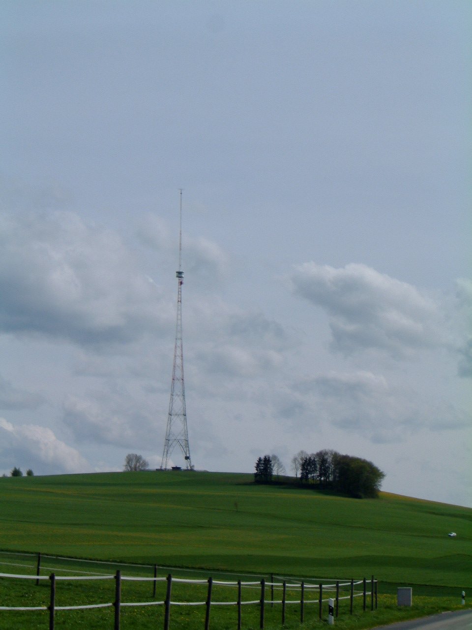
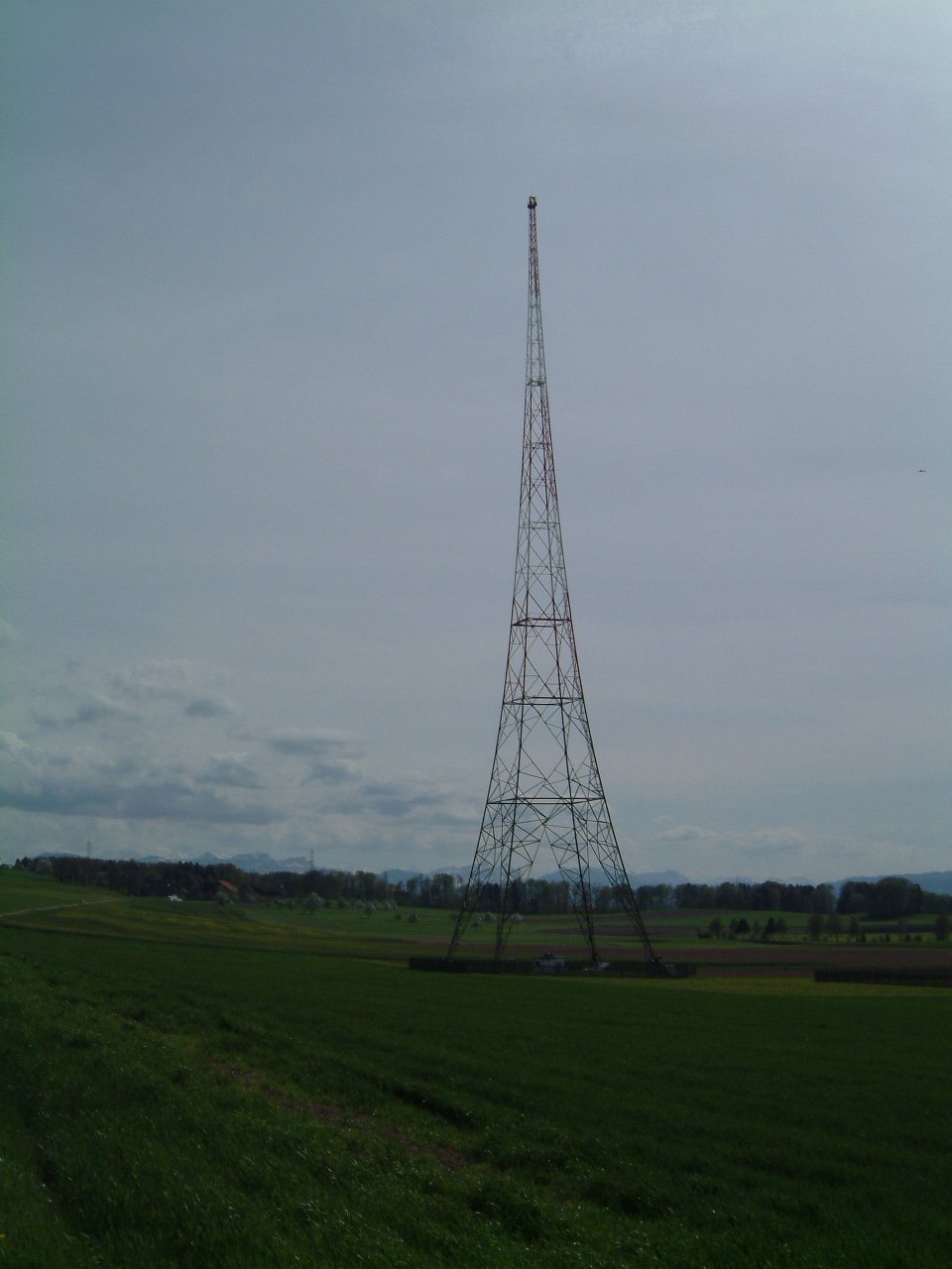
East view of the main antenna. (Apr. 2003)
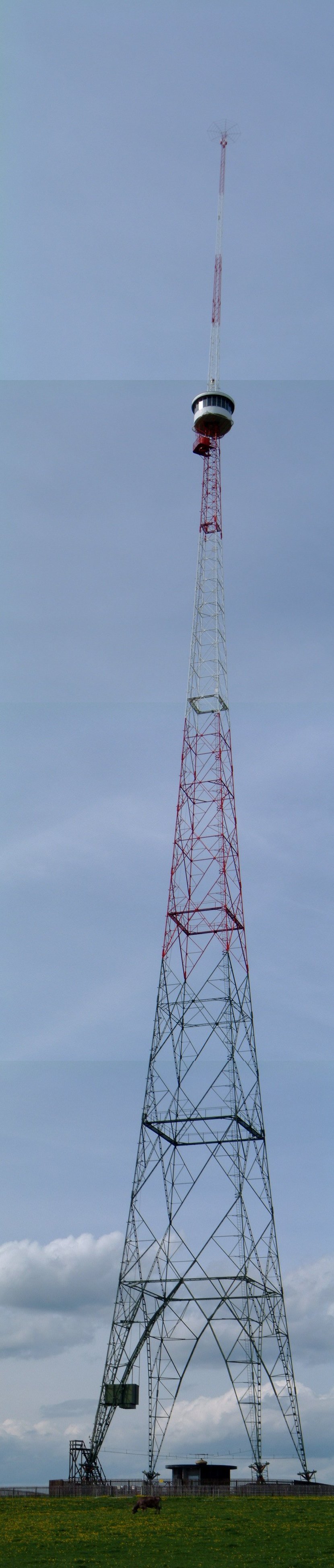
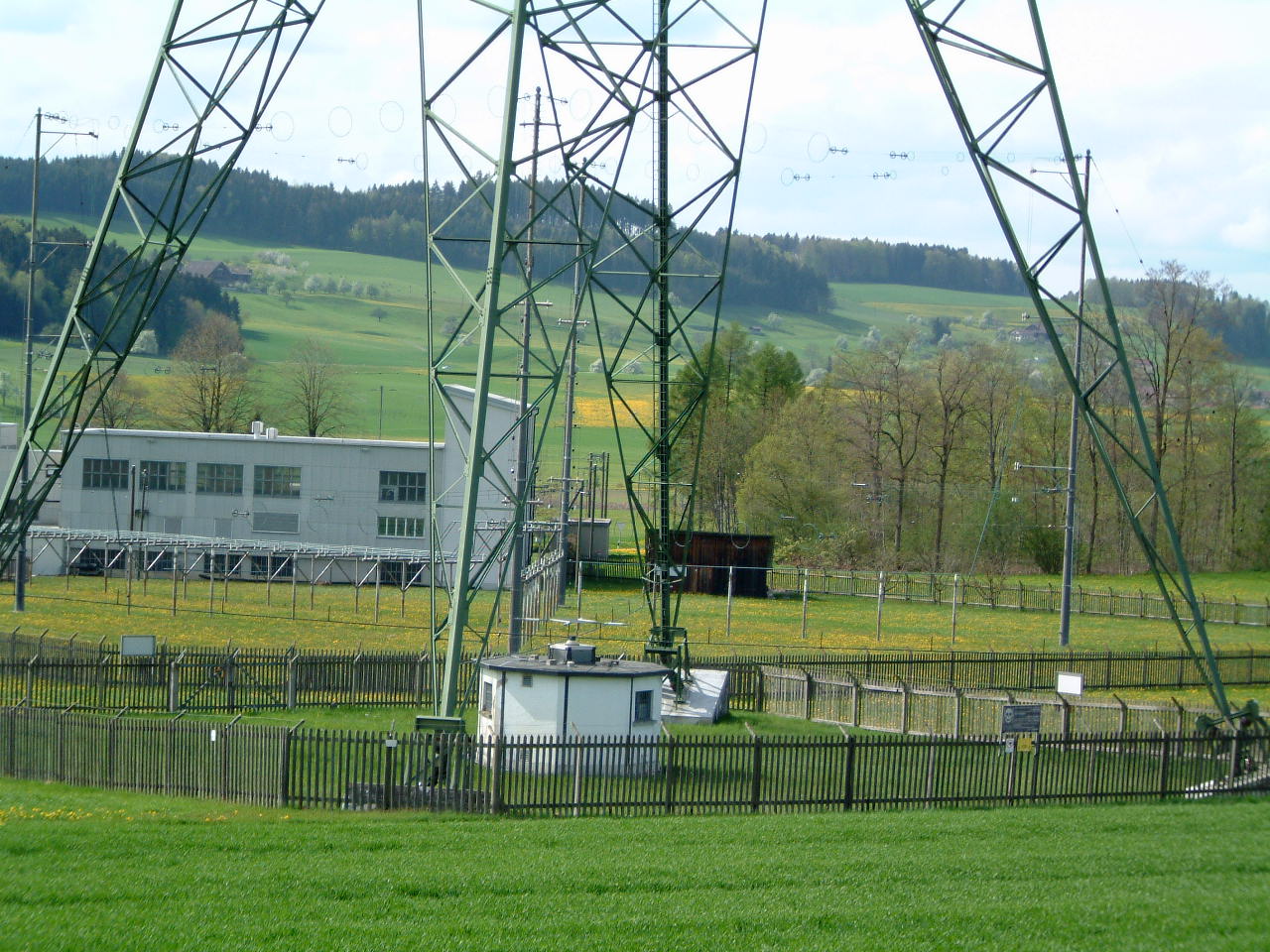
Detail view of the main antenna. (Apr. 2003)
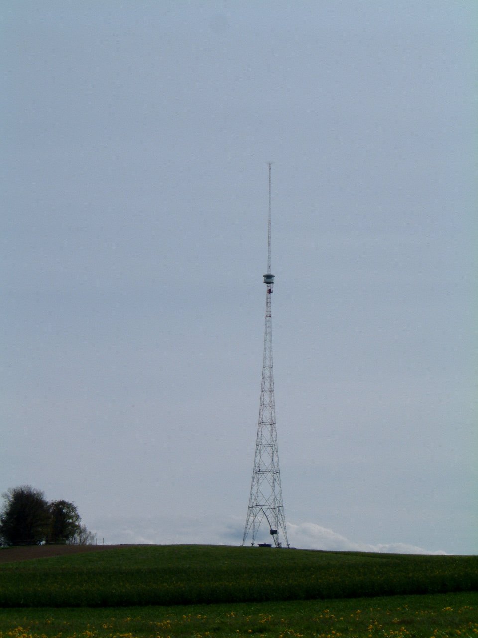
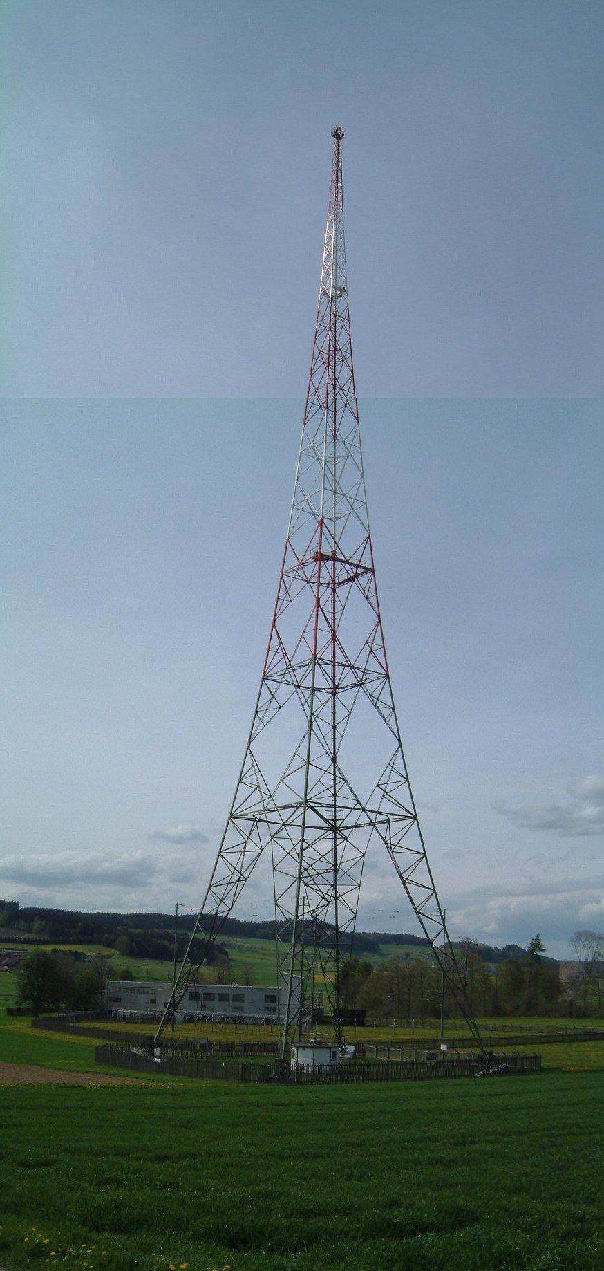
West view of the main antenna. (Apr. 2003)
| Location: | E 8° 10' 31.58" / N 47° 11' 22.66" |
| Frequency: | Transmitter is off (used to be 531 kHz). |
| Wavelength: | Transmitter is off (used to be 565 m). |
| Power: | Transmitter is off (used to be 500 kW). |
| Call-sign: | Used to be "Schweizer Radio DRS". |
| Transmission type: | Used to be a medium wave AM broadcast station. |
The Beromünster transmitter started broadcasting on May 1st, 1931 with a power of 60 kW and a frequency of 556 kHz (539.6 m). In 1933 the power was increased to 100 kW. In 1939 a new anti-fading antenna was built. In 1947 the power was increased to 200 kW. In 1948 as a consequence of the Copenhagen frequency plan, the transmitter was moved to 529 kHz (567.1 m). In 1969 a new transmitter capable of 500 kW was installed, but was used at full-power only at night until 1971 when the power was full time 500 kW. Starting 1968, Beromünster also transmitted on 1562 kHz (192.1 m) for a few years. In 1978, because of the Geneva frequency plan, the frequency was changed to 531kHz (565m). The transmitter was switched off in December 2008.
Starting in 1966, two 250 kW and one 100 kW short-waves transmitters were operating for several years from this site.
| Tower type: | 215 m self supporting tower. |
| Antenna type: | Shortened λ/2 vertical tower with inductor at 150 m above ground and top capacitive hat. Isolated from ground. |
| Feed point: | Base of the tower. |
Even if the transmitter was switched off in December 2008, the tower still exists (Dec. 2016).
East view of the main antenna. (Apr. 2003) |
Detail view of the main antenna. (Apr. 2003) |
West view of the main antenna. (Apr. 2003) |
| Tower type: | 126 m self supporting tower. |
| Antenna type: | λ/4 vertical antenna, isolated from ground. |
| Feed point: | Base of the tower. |
The transmitter was switched off in December 2008: this tower has been dismantled in Aug. 2011.
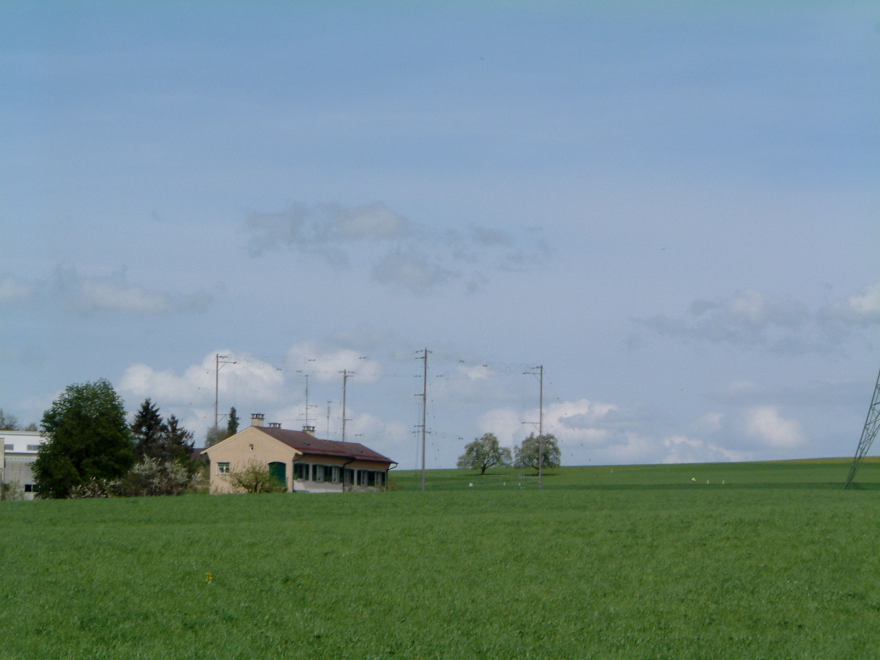
 South view of the spare antenna. (Apr. 2003) |
 North view of the spare antenna. (Apr. 2003) |
 Match box and feed point. (Apr. 2003) |
 Detail view of the spare antenna. (Apr. 2003) |
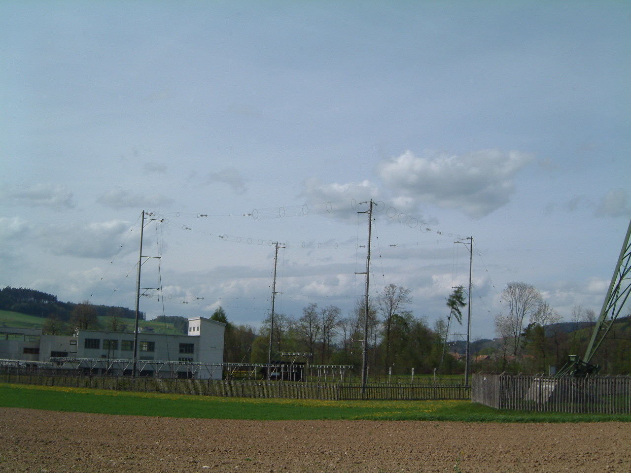
| Tower types: | Corner cage dipoles, suspended between poles. (Apr. 2003) |
| Antenna type: | Several horizontal dipoles, one for each band. (Apr. 2003) |
| Feed point: | Balanced line. (Apr. 2003) |
These antennas were dismantled and no longer exist.
 South view of the short spare dipoles. (Apr. 2003) |
 North view of the short spare dipoles. (Apr. 2003) |
 Long spare dipoles. (Apr. 2003) |
|